pcDuino 프로그래밍 가이드
본 게시물에서는 Python 및 C++ 프로그래밍 언어를 이용하여 pcDuino의 다양한 리소스에 접근하는 법을 설명할 것입니다.
C++ 프로그래밍 - Hello World
pcDuino는 Ubuntu 리눅스 플랫폼이기 때문에 pcDuino에서 C++ 프로그래밍을 하는 것은 여느 리눅스OS에서 프로그래밍 하는 거과 동일합니다. 소스코드를 작성하고 g++컴파일러를 이용하여 컴파일을 하는 것이죠. vi나 LeafPad와 같은 텍스트 에디터를 이용하여 아래와 같은 코드를 입력합니다. #include // Include the standard IO library.
int main(void) // For C++, main *must* return type int!
{
printf("Hello, world!\n"); // Print "Hello, world!" string to the command line.
}
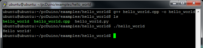
작성된 소스코드를 "hello_world.cpp" 로 저장하고, 터미널 윈도우를 열어 쉘로 들어갑니다. 작성한 소스코드의 디렉토리로 이동하여 아래의 명령으로 소스코드를 컴파일합니다. g++ hello_world.cpp -o hello_world // 소스코드 컴파일 명령
./hello_world // 컴파일된 실행파일 실행
아래는 터미널 창에서 위의 명령을 실행하였을때 나오는 화면입니다.
Python 프로그래밍 - Hello World
Python은 C++에 비해서 상대적으로 쉬운 프로그래밍 언어로 인터프리터 언어입니다. 인터프리터 언어는 프로그래머가 입력한 한줄 한줄이 바로 실행되기 때문에 컴파일 절차가 필요가 없습니다. 바로바로 실행되기 때문에 좀 느려지는 단점이 있지만 Python의 강력한 라이브러들을 생각하면 Python은 매우 훌륭한 프로그래밍 언어입니다.
다시 텍스트 에디터를 열고 아래를 입력합니다. print "Hello, world!"
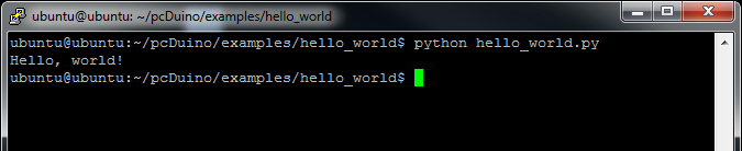
"hello_world.py" 라는 이름으로 저장한 후 터미널 창을 열고 아래의 명령을 수행합니다. python hello_world.py
출력은 아래와 같습니다.
GPIO 핀 사용하기
pcDuino는 18개의 GPIO핀을 가지고 있습니다. pcDuino의 GPIO핀을 접근하는 것은 크게 어렵지 않습니다. pcDuino에는 GPIO 핀에 연결된 각각의 고유한 파일들이 있는데, 접근하고자 하는 GPIO핀에 해당하는 파일을 열고 읽거나 쓰면 GPIO를 읽고 쓸수 있습니다. (참고로 리눅스는 모든 입출력을 파일로 관리합니다) 그러한 파일은 아래의 위치에 있습니다. /sys/devices/virtual/misc/gpio/mode/
/sys/devices/virtual/misc/gpio/pin/
파일은 총 20개가 있는데 그중 18개만 실제적으로 사용가능한 핀에 매핑되어 있습니다. 파일맵에 대한 핀은 아래와 같습니다.
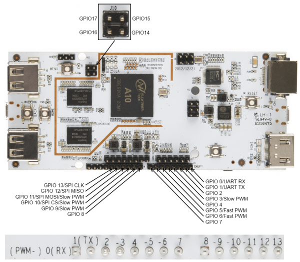
몇몇 핀들은 두세개의 역활로 사용이 가능한데, mode 파일에 특정 문자열을 써줌으로써 사용하고자 하는 핀의 시리얼, SPI, 입력, 출력 등의 다양한 모드를 활성화 시킬 수 있습니다. 예를 들어 아래와 같은 문자를 입력하면
- '0' - 핀을 입력으로 설정
- '1' - 핀을 출력으로 설정
- '8' - 핀을 입력으로 설정하고 풀업저항 설정
pcDuino의 GPIO핀은 3.3v 이기때문에 5v를 인가하면 장치가 고장이 날수 있습니다. 주의 요망됩니다. 출력 전류 캐파는 그리 높지 않습니다만 작은 LED는 충분히 동작시킬수 있는 정도입니다.
C++ 언어로 GPIO 제어하기
아래는 C++을 이용하여 GPIO핀을 읽고 쓰는 소스 예제입니다. GPIO2포트에 연결되어 있는 버튼이 눌리기(핀 로우)를 기다렸다가 GPIO핀에 연결된 LED를 켜는 프로그램입니다. #include
#include
#include
#include
#include "gpio_test.h"
// These arrays will become file descriptors for the 18 IO pin and mode files.
int pinMode[18];
int pinData[18];
int main(void)
{
int i = 0; // Loop iterator
char inputBuffer = HIGH; // create and clear a buffer for data from pins
char path[256]; // nice, long buffer to hold the path name for pin access
// This first loop does four things:
// - initialize the file descriptors for the pin mode files
// - initialize the file descriptors for the pin data files
// - make the pins outputs
// - set all the pins low
for (i = 2; i <= 17; i++)
{
// Clear the path variable...
memset(path,0,sizeof(path));
// ...then assemble the path variable for the current pin mode file...
sprintf(path, "%s%s%d", GPIO_MODE_PATH, GPIO_FILENAME, i);
// ...and create a file descriptor...
pinMode[i] = open(path, O_RDWR);
// ...then rinse, repeat, for the pin data files.
memset(path,0,sizeof(path));
sprintf(path, "%s%s%d", GPIO_PIN_PATH, GPIO_FILENAME, i);
pinData[i] = open(path, O_RDWR);
// Now that we have descriptors, make the pin an output, then set it low.
setPinMode(pinMode[i], OUTPUT);
setPin(pinData[i], LOW);
printf("Pin %d low\n", i); // Print info to the command line.
}
// Now, we're going to wait for a button connected to pin 2 to be pressed
// before moving on with our demo.
setPinMode(pinMode[2], INPUT_PU);
do
{
printf("Waiting for button press...\n");
// This lseek() is very important- must read from the top of the file!
lseek(pinData[2], 0, SEEK_SET);
// Read one byte from the pinData register. The first byte will be '1' if
// the pin is high and '0' if it is low.
read(pinData[2], &inputBuffer, 1);
usleep(100000); // Sleep for 1/10 second.
} while (inputBuffer == HIGH);
// After the button press, let's scan through and turn the lights on one
// at a time, the back off again. After that, we're done.
for (i = 3; i <= 17; i++)
{
setPin(pinData[i], HIGH);
printf("Pin %d HIGH\n", i);
usleep(250000);
}
for (i = 17; i >=3; i--)
{
setPin(pinData[i], LOW);
printf("Pin %d LOW\n", i);
usleep(250000);
}
}
// These two 'set' functions are just wrappers to the writeFile() function to
// make the code prettier.
void setPinMode(int pinID, int mode)
{
writeFile(pinID, mode);
}
void setPin(int pinID, int state)
{
writeFile(pinID, state);
}
// While it seems okay to only *read* the first value from the file, you
// seemingly must write four bytes to the file to get the I/O setting to
// work properly. This function does that.
void writeFile(int fileID, int value)
{
char buffer[4]; // A place to build our four-byte string.
memset((void *)buffer, 0, sizeof(buffer)); // clear the buffer out.
sprintf(buffer, "%c", value);
lseek(fileID, 0, SEEK_SET); // Make sure we're at the top of the file!
write(fileID, buffer, sizeof(buffer));
}
Python으로 GPIO제어하기
위와 동일한 기능을 하는 소스코드의 파이썬 버전입니다. GPIO2의 버튼이 눌리기를 기다리고, 다른 GPIO핀을 스캔하는 프로그램입니다. #!/usr/bin/env python
import time, os
## For simplicity's sake, we'll create a string for our paths.
GPIO_MODE_PATH= os.path.normpath('/sys/devices/virtual/misc/gpio/mode/')
GPIO_PIN_PATH=os.path.normpath('/sys/devices/virtual/misc/gpio/pin/')
GPIO_FILENAME="gpio"
## create a couple of empty arrays to store the pointers for our files
pinMode = []
pinData = []
## Create a few strings for file I/O equivalence
HIGH = "1"
LOW = "0"
INPUT = "0"
OUTPUT = "1"
INPUT_PU = "8"
## First, populate the arrays with file objects that we can use later.
for i in range(0,18):
pinMode.append(os.path.join(GPIO_MODE_PATH, 'gpio'+str(i)))
pinData.append(os.path.join(GPIO_PIN_PATH, 'gpio'+str(i)))
## Now, let's make all the pins outputs...
for pin in pinMode:
file = open(pin, 'r+') ## open the file in r/w mode
file.write(OUTPUT) ## set the mode of the pin
file.close() ## IMPORTANT- must close file to make changes!
## ...and make them low.
for pin in pinData:
file = open(pin, 'r+')
file.write(LOW)
file.close()
## Next, let's wait for a button press on pin 2.
file = open(pinMode[2], 'r+') ## accessing pin 2 mode file
file.write(INPUT_PU) ## make the pin input with pull up
file.close() ## write the changes
temp = [''] ## a string to store the value
file = open(pinData[2], 'r') ## open the file
temp[0] = file.read() ## fetch the pin state
## Now, wait until the button gets pressed.
while '0' not in temp[0]:
file.seek(0) ## *MUST* be sure that we're at the start of the file!
temp[0] = file.read() ## fetch the pin state
print "Waiting for button press..."
time.sleep(.1) ## sleep for 1/10 of a second.
file.close() ## Make sure to close the file when you're done!
## Now, for the final trick, we're going to turn on all the pins, one at a
## time, then turn them off again.
for i in range(3,17):
file = open(pinData[i], 'r+')
file.write(HIGH)
file.close()
time.sleep(.25)
for i in range(17,2, -1):
file = open(pinData[i], 'r+')
file.write(LOW)
file.close()
time.sleep(.25)
라즈베리 파이와는 다르게 pcDuino는 몇개의 아날로그 입출력 핀을 가지고 있습니다. (아래 그림 참조)
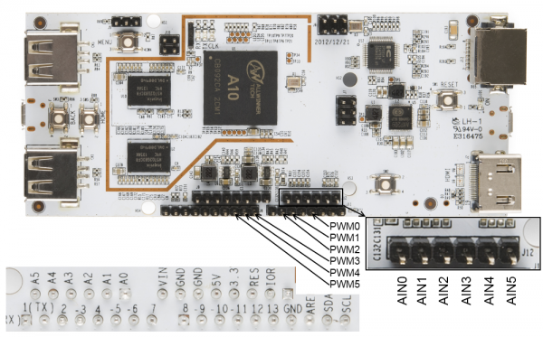
pcDuino에서 아날로그 출력은 PWM에 의해 이루어 지게 됩니다. pcDuino에는 여섯개의 PWM 가능 핀들(3, 5, 6, 9, 10, 11)이 있습니다. (참고로 이 핀들은 아두이노의 PWM핀과 동일한 위치입니다.) 핀 5번과 6번은 true 520Hz 8bit PWM이며 나머지들은 5Hz에서 0~20 의 범위로 제한됩니다. 모든 핀들의 하이레벨 출력은 3.3V입니다.
아날로그 입력은 A0에서 A5 핀을 통해서 이루어 집니다. A0와 A1핀은 6비트 입력으로 0-2V 범위에서 0-63의 값을 리턴하고, A2-A5 핀은 12비트 입력으로 3.3v 전체 범위에서 동작합니다. AREF 셋팅은 현재 시점으로 아직 지원하지 않습니다.
C++ 언어로 아날로그 핀 제어하기
아날로그 입력은 표준 파일 스트림 입력을 통하여 처리가 됩니다. 단순히 파일을 열고 값을 읽으면 됩니다. 값은 스트링으로 읽히기 때문에 문자열을 숫자로 바꾸어 주는 atoi()함수가 필요합니다.
아날로그 출력은 코맨드 라인 인터페이스를 통해 처리됩니다. system() 함수 호출을 통해 특정 파일에 값을 pipe 하여 핀에 PWM레벨을 셋팅할 수 있습니다. (파일스트림은 동작안함)
아래의 예제는 PWM핀을 off에서 on으로 서서히 변화시키고, 아날로그 입력의 값을 출력하는 예제입니다. #include
#include
#include
#include
#include
#include "analog.h"
int adc[6]; // Array for file descriptors for the adc pins
int PWMMaxVal[6]; // Store the max values for the PWM outputs
char path[64]; // Nice big buffer for constructing file paths
int main(void)
{
// For starters, let's create file descriptors for all the ADC pins. PWM is
// handled differently; see the analogWrite() function for details.
for(int i = 0; i<= 5; i++)
{
memset(path, 0, sizeof(path));
sprintf(path, "%s%s%d", ADC_IF_PATH, ADC_IF_FILE , i);
adc[i] = open(path, O_RDONLY);
memset(path, 0, sizeof(path));
sprintf(path, "%s%s%d/%s", PWM_IF_PATH, PWM_IF_FILE , i, PWM_MAX);
int PWMMaxFD = open(path, O_RDONLY);
char PWMMaxStr[4];
read(PWMMaxFD, PWMMaxStr, sizeof(PWMMaxStr));
PWMMaxVal[i] = atoi(PWMMaxStr);
}
// Now, we'll blast all the PWM pins to zero.
for(int j = 0; j<=5; j++)
{
analogWrite(j, 0);
}
// Now we can go about the business of dimming some LEDs.
for(int j = 0; j<=5; j++)
{
for(int i = 0; i<=255; i++)
{
analogWrite(j, i);
usleep(10000);
}
analogWrite(j, 0);
}
// Analog input is handled by file streams.
for (int i = 0; i <= 5; i++)
{
char ADCBuffer[16];
lseek(adc[i], 0, SEEK_SET);
int res = read(adc[i], ADCBuffer, sizeof(ADCBuffer));
int ADCResult = atoi(ADCBuffer);
printf("ADC Channel: %d Value: %s", i, ADCBuffer);
}
}
// PWM pin access is handled by
// using the system() command to invoke the command process to execute a
// command. We assemble the command using sprintf()- the command takes
// the form
// echo > /sys/class/leds/pwmX/brightness
// where should be replaced by an integer from 0-255 and X should
// be replaced by an index value from 0-5
void analogWrite(int pin, int value)
{
memset(path, 0, sizeof(path));
value = (PWMMaxVal[pin] * value)/255;
sprintf(path, "echo %d > %s%s%d/%s", value, PWM_IF_PATH, PWM_IF_FILE, \
pin, PWM_IF);
system(path);
}
Python으로 아날로그 핀 제어하기
아래는 위의 C++ 예제의 파이썬 버전입니다. #!/usr/bin/env python
import time, os
## For simplicity's sake, we'll create a strings and filenames for our paths
ADC_PATH= os.path.normpath('/proc/')
ADC_FILENAME = "adc"
PWM_PATH= os.path.normpath('/sys/class/leds/')
PWM_DIR = "pwm"
PWM_FILENAME = "brightness"
PWM_MAX = "max_brightness"
## create empty arrays to store the pointers for our files
adcFiles = []
pwmFiles = []
pwmMaxFiles = []
## create an empty array to store the maximum value for each channel of PWM
pwmMaxVal = []
## Populate the arrays with paths that we can use later.
for i in range(0,6):
adcFiles.append(os.path.join(ADC_PATH, ADC_FILENAME+str(i)))
pwmFiles.append(os.path.join(PWM_PATH, PWM_DIR+str(i), PWM_FILENAME))
pwmMaxFiles.append(os.path.join(PWM_PATH, PWM_DIR+str(i), PWM_MAX))
## Now, let's scan the PWM directories and pull out the values we should use
## for the maximum PWM level.
for file in pwmMaxFiles:
fd = open(file, 'r')
pwmMaxVal.append(int(fd.read(16)))
fd.close()
## Let's dim some LEDs! The method for controlling a PWM pin on the pcDuino is
## to send to the command interpreter (via os.system() this command:
## echo > /sys/class/leds/pwmX/brightness
## where varies from 0 to the maximum value found in the
## max_brightness file, and X can be from 0-5.
for file in pwmFiles:
j = pwmFiles.index(file) ## extract the PWM limit for this LED
for i in range (0,pwmMaxVal[j]):
os.system("echo " + str(i) + " >" + file)
time.sleep(.01)
os.system("echo 0 >" + file)
## Reading ADC values is a little more straightforward than PWM- it's just
## classic OS file reads. Note that the value that comes out of the file is
## a string, so you'll need to format it with int() if you want to do math
## with that value later on!
for file in adcFiles:
fd = open(file, 'r')
fd.seek(0)
print "ADC Channel: " + str(adcFiles.index(file)) + " Result: " + fd.read(16)
fd.close()
시리얼 통신
pcDuino는 여러개의 시리얼 포트를 가지고 있습니다. 프로그램상에서 어떻게 시리얼포트에서 데이터를 주고 받을 수 있는지 살펴보겠습니다.
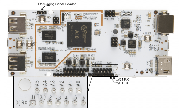
pcDuino의 A10 프로세서는 여덟개의 시리얼 포트를 가지고 있습니다만 두개의 포트만이 리눅스 장치에 매핑되어 있습니다. /dev/ttyS0는 디버깅 포트에, /dev/ttyS1은 UART로 매핑되어 있습니다.
핀 모드 셋팅
핀을 시리얼 통신용으로 사용하기 위해서는 핀의 모드를 변경하여야 합니다. 핀 0번과 1번의 모드파일에 '3'을 써서 핀 모드를 변경합니다. C++에서는 코드에서 변경을 해주어야 하지만 파이썬에서는 시리얼 라이브러리가 디폴트로 수행합니다.
C++로 시리얼 통신하기
C++을 이용하여 시리얼 통신을 하는 것은 파이선에 비해 다소 어렵습니다만 리눅스에서 시리얼 통신을 하는 방법을 다루는 많은 참고 자료들이 인터넷에 있으니, 여기서는 간단한 예제를 살펴보도록 하겠습니다. 아래의 코드는 대부분 시리얼 통신을 하기 위한 포트 설정이며, 시리얼 포트를 설정한 후 "Hello, world!"를 보내고 키입력을 기다리는 예제 입니다. #include
#include
#include
#include
#include
#include
#include "serial_test.h"
// Life is easier if we make a constant for our port name.
static const char* portName = "/dev/ttyS1";
int main(void)
{
// The very first thing we need to do is make sure that the pins are set
// to SERIAL mode, rather than, say, GPIO mode.
char path[256];
for (int i = 0; i<=1; i++)
{
// Clear the path variable...
memset(path,0,sizeof(path));
// ...then assemble the path variable for the current pin mode file...
sprintf(path, "%s%s%d", GPIO_MODE_PATH, GPIO_FILENAME, i);
// ...and create a file descriptor...
int pinMode = open(path, O_RDWR);
// ...which we then use to set the pin mode to SERIAL...
setPinMode(pinMode, SERIAL);
// ...and then, close the pinMode file.
close(pinMode);
}
int serialPort; // File descriptor for serial port
struct termios portOptions; // struct to hold the port settings
// Open the serial port as read/write, not as controlling terminal, and
// don't block the CPU if it takes too long to open the port.
serialPort = open(portName, O_RDWR | O_NOCTTY | O_NDELAY );
// Fetch the current port settings
tcgetattr(serialPort, &portOptions);
// Flush the port's buffers (in and out) before we start using it
tcflush(serialPort, TCIOFLUSH);
// Set the input and output baud rates
cfsetispeed(&portOptions, B115200);
cfsetospeed(&portOptions, B115200);
// c_cflag contains a few important things- CLOCAL and CREAD, to prevent
// this program from "owning" the port and to enable receipt of data.
// Also, it holds the settings for number of data bits, parity, stop bits,
// and hardware flow control.
portOptions.c_cflag |= CLOCAL;
portOptions.c_cflag |= CREAD;
// Set up the frame information.
portOptions.c_cflag &= ~CSIZE; // clear frame size info
portOptions.c_cflag |= CS8; // 8 bit frames
portOptions.c_cflag &= ~PARENB;// no parity
portOptions.c_cflag &= ~CSTOPB;// one stop bit
// Now that we've populated our options structure, let's push it back to the
// system.
tcsetattr(serialPort, TCSANOW, &portOptions);
// Flush the buffer one more time.
tcflush(serialPort, TCIOFLUSH);
// Let's write the canonical test string to the serial port.
write(serialPort, "Hello, World!", 13);
// Now, let's wait for an input from the serial port.
fcntl(serialPort, F_SETFL, 0); // block until data comes in
char dataIn = 0;
do
{
read(serialPort,&dataIn,1);
} while(dataIn == 0);
printf("You entered: %c\n", dataIn);
// Don't forget to close the port! Failing to do so can cause problems when
// attempting to execute code in another program.
close(serialPort);
}
void setPinMode(int pinID, int mode)
{
writeFile(pinID, mode);
}
// While it seems okay to only *read* the first value from the file, you
// seemingly must write four bytes to the file to get the I/O setting to
// work properly. This function does that.
void writeFile(int fileID, int value)
{
char buffer[4]; // A place to build our four-byte string.
memset((void *)buffer, 0, sizeof(buffer)); // clear the buffer out.
sprintf(buffer, "%d", value);
lseek(fileID, 0, SEEK_SET); // Make sure we're at the top of the file!
int res = write(fileID, buffer, sizeof(buffer));
}
파이선에서 시리얼 통신하기
파이선에서 시리얼 통신을 하려면 외부 라이브러리가 필요합니다. 아래와 같이 터미널 창에 입력 하면 간단하게 설치가 됩니다. sudo apt-get install python-serial
파리선 시리얼 라이브러리인 Pyserial이 자동으로 설치가 되면 아래와 같은 코드를 입력합니다. 동작은 C++코드와 같습니다. #!/usr/bin/env python
import serial ## Load the serial library
## Select and configure the port
myPort = serial.Serial('/dev/ttyS1', 115200, timeout = 10)
## Dump some data out of the port
myPort.write("Hello, world!")
## Wait for data to come in- one byte, only
x = myPort.read()
## Echo the data to the command prompt
print "You entered " + x
## Close the port so other applications can use it.
myPort.close()
I2C 통신
I2C 통신하기는 pcDuino에서 매우 쉽습니다.
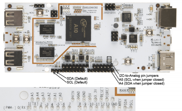
pcDuino에는 여러개의 I2C 버스 장치가 있지만 사용자에게는 단 한개(/dev/i2c-2)만 사용이 가능하게 되어 있습니다. 반드시 알아야 할 아주 중요한 사항중 하나는 I2C버스의 속도는 200KHz로 고정되어 있다는 사실입니다. 이는 몇몇 I2C장치들은 pcDuino에서 동작하지 않을 수 있다는 것을 의미합니다. 버스의 속도는 드라이버를 컴파일할때 고정되며 사용자 영역에서는 변경할 수 가 없습니다.
pcDuino는 보드상에 2.2k 풀업 저항들을 가지고 있습니다. 이것들은 아두이노 우노 R3 이후 보드들과 같은 위치의 아두이노 스타일 헤더 핀에 연결되어 있습니다. 예전 보드에서 핀들은 아날로그 핀 4번과 5번과 공유되었습니다. pcDuino에서는 솔더 점퍼가 있어 원한다면 SDA와 SCL라인을 리다이렉트 할 수 있습니다.
코드를 작성하지 않고 I2C버스를 제어할 수 있는 툴이 있습니다. 이 툴을 설치 하기 위해 아래의 명령을 실행합니다.
sudo apt-get install i2c-tools
C++로 I2C 통신하기
아래의 간단한 프로그램은 여러개의 장치를 I2C포트에 연결하여 장치ID 레지스터를 읽고, 쉘상에 프린트하는 예제입니다. #include
#include
#include
#include
#include
#include
#include
#include
int main(void)
{
// Set up some variables that we'll use along the way
char rxBuffer[32]; // receive buffer
char txBuffer[32]; // transmit buffer
int gyroAddress = 0x68; // gyro device address
int xlAddress = 0x53; // accelerometer device address
int tenBitAddress = 0; // is the device's address 10-bit? Usually not.
int opResult = 0; // for error checking of operations
// Create a file descriptor for the I2C bus
int i2cHandle = open("/dev/i2c-2", O_RDWR);
// Tell the I2C peripheral that the device address is (or isn't) a 10-bit
// value. Most probably won't be.
opResult = ioctl(i2cHandle, I2C_TENBIT, tenBitAddress);
// Tell the I2C peripheral what the address of the device is. We're going to
// start out by talking to the gyro.
opResult = ioctl(i2cHandle, I2C_SLAVE, gyroAddress);
// Clear our buffers
memset(rxBuffer, 0, sizeof(rxBuffer));
memset(txBuffer, 0, sizeof(txBuffer));
// The easiest way to access I2C devices is through the read/write
// commands. We're going to ask the gyro to read back its "WHO_AM_I"
// register, which contains the I2C address. The process is easy- write the
// desired address, the execute a read command.
txBuffer[0] = 0x00; // This is the address we want to read from.
opResult = write(i2cHandle, txBuffer, 1);
if (opResult != 1) printf("No ACK bit!\n");
opResult = read(i2cHandle, rxBuffer, 1);
printf("Part ID: %d\n", (int)rxBuffer[0]); // should print 105
// Next, we'll query the accelerometer using the same process- but first,
// we need to change the slave address!
opResult = ioctl(i2cHandle, I2C_SLAVE, xlAddress);
txBuffer[0] = 0x00; // This is the address to read from.
opResult = write(i2cHandle, txBuffer, 1);
if (opResult != 1) printf("No ACK bit!\n");
opResult = read(i2cHandle, rxBuffer, 1);
printf("Part ID: %d\n", (int)rxBuffer[0]); // should print 229
}
파이선으로 I2C통신하기
파신썬은 pySerial 라이브러이와 같은 지원 패키지를 가지고 있어 I2C 장치를 쉽게 연결할 수 있습니다. 설치하려면 터미널 창에서 아래의 명령어를 입력하십시오. sudo apt-get install python-smbus
SMBus는 PC 머더보드에서 사용되는 I2C 파생 통신에게 주어진 이름으로, 차이점은 하드웨어이며 사용자 코딩 레벨에서는 차이점이 없습니다. 아래의 코드는 위의 c++코드와 동작이 같습니다. #!/usr/bin/env python
import smbus
## As before, we'll create an alias for our addresses, just to make things
## a bit easier and more readable later on.
gyroAddress = 0x68
xlAddress = 0x53
## Initialize an smbus object. The parameter passed is the number of the I2C
## bus; for the Arduino-ish headers on the pcDuino, it will be "2".
i2c = smbus.SMBus(2)
## With both of these devices, the first byte written specifies the address of
## the register we want to read or write; for both devices, the device ID is
## stored in location 0. Writing that address, than issuing a read, will
## give us our answer.
i2c.write_byte(gyroAddress, 0)
print "Device ID: " + str(i2c.read_byte(gyroAddress)) ## should be 105
i2c.write_byte(xlAddress, 0)
print "Device ID: " + str(i2c.read_byte(xlAddress)) ## should be 229
SPI 통신
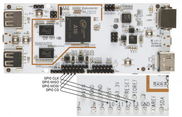
사용가능한 SPI0은 네개의 핀을 통하여 접근이 가능합니다. 이 핀들은 프로세서의 MOSI, MISO, SCK, CS라인과 연결되어 Full SPI통신이 가능합니다.
C++로 SPI 프로그래밍하기
핀의 모드파일를 열어 SPI모드로 핀의 모드를 변경합니다.
spidev0.0에 대한 파일 디스크립터를 열고 ioctl()을 이용하여 /linux/spi/spidev.h 에 정의된 설정을 장치에 전달합니다. 메세지를 전달하기 위해서는 구조체를 만들고 구조체를 ioctrl()을 이용하여 파일 디스크립터에 전달합니다. #include
#include
#include
#include
#include
#include
#include "spi_test.h"
static const char *spi_name = "/dev/spidev0.0";
int main(void)
{
int res = 0; // We can use this to monitor the results of any operation.
// The very first thing we need to do is make sure that the pins are set
// to SPI mode, rather than, say, GPIO mode.
char path[256];
for (int i = 10; i<=13; i++)
{
// Clear the path variable...
memset(path,0,sizeof(path));
// ...then assemble the path variable for the current pin mode file...
sprintf(path, "%s%s%d", GPIO_MODE_PATH, GPIO_FILENAME, i);
// ...and create a file descriptor...
int pinMode = open(path, O_RDWR);
// ...which we then use to set the pin mode to SPI...
setPinMode(pinMode, SPI);
// ...and then, close the pinMode file.
close(pinMode);
}
// As usual, we begin the relationship by establishing a file object which
// points to the SPI device.
int spiDev = open(spi_name, O_RDWR);
// We'll want to configure our SPI hardware before we do anything else. To do
// this, we use the ioctl() function. Calls to this function take the form
// of a file descriptor, a "command", and a value. The returned value is
// always the result of the operation; pass it a pointer to receive a value
// requested from the SPI peripheral.
// Start by setting the mode. If we wanted to *get* the mode, we could
// use SPI_IOC_RD_MODE instead. In general, the "WR" can be replaced by
// "RD" to fetch rather than write. Also note the somewhat awkward
// setting a variable rather than passing the constant. *All* data sent
// via ioctl() must be passed by reference!
int mode = SPI_MODE0;
ioctl(spiDev, SPI_IOC_WR_MODE, &mode);
// The maximum speed of the SPI bus can be fetched. You'll find that, on the
// pcDuino, it's 12MHz.
int maxSpeed = 0;
ioctl(spiDev, SPI_IOC_RD_MAX_SPEED_HZ, &maxSpeed);
printf("Max speed: %dHz\n", maxSpeed);
// In rare cases, you may find that a device expects data least significant
// bit first; in that case, you'll need to set that up. Writing a 0
// indicates MSb first; anything else indicates LSb first.
int lsb_setting = 0;
ioctl(spiDev, SPI_IOC_WR_LSB_FIRST, &lsb_setting);
// Some devices may require more than 8 bits of data per transfer word. The
// SPI_IOC_WR_BITS_PER_WORD command allows you to change this; the default,
// 0, corresponds to 8 bits per word.
int bits_per_word = 0;
ioctl(spiDev, SPI_IOC_WR_BITS_PER_WORD, &bits_per_word);
// Okay, now that we're all set up, we can start thinking about transferring
// data. This, too, is done through ioctl(); in this case, there's a special
// struct (spi_ioc_transfer) defined in spidev.h which holds the needful
// info for completing a transfer. Its members are:
// * tx_buf - a pointer to the data to be transferred
// * rx_buf - a pointer to storage for received data
// * len - length in bytes of tx and rx buffers
// * speed_hz - the clock speed, in Hz
// * delay_usecs - delay between last bit and deassertion of CS
// * bits_per_word - override global word length for this transfer
// * cs_change - strobe chip select between transfers?
// * pad - ??? leave it alone.
// For this example, we'll be reading the address location of an ADXL362
// accelerometer, then writing a value to a register and reading it back.
// We'll do two transfers, for ease of data handling: the first will
// transfer the "read register" command (0x0B) and the address (0x02), the
// second will dump the response back into the same buffer.
struct spi_ioc_transfer xfer;
memset(&xfer, 0, sizeof(xfer));
char dataBuffer[3];
char rxBuffer[3];
dataBuffer[0] = 0x0B;
dataBuffer[1] = 0x02;
dataBuffer[2] = 0x00;
xfer.tx_buf = (unsigned long)dataBuffer;
xfer.rx_buf = (unsigned long)rxBuffer;
xfer.len = 3;
xfer.speed_hz = 500000;
xfer.cs_change = 1;
xfer.bits_per_word = 8;
res = ioctl(spiDev, SPI_IOC_MESSAGE(1), &xfer);
printf("SPI result: %d\n", res);
printf("Device ID: %d - %d - %d\n", rxBuffer[2], rxBuffer[1], rxBuffer[0]);
}
void setPinMode(int pinID, int mode)
{
writeFile(pinID, mode);
}
// While it seems okay to only *read* the first value from the file, you
// seemingly must write four bytes to the file to get the I/O setting to
// work properly. This function does that.
void writeFile(int fileID, int value)
{
char buffer[4]; // A place to build our four-byte string.
memset((void *)buffer, 0, sizeof(buffer)); // clear the buffer out.
sprintf(buffer, "%d", value);
lseek(fileID, 0, SEEK_SET); // Make sure we're at the top of the file!
int res = write(fileID, buffer, sizeof(buffer));
}
파이썬으로 SPI 프로그래밍하기
파이썬에서는 SPI 통신을 쉽게 하기 위한 패키지가 존재합니다. 아래와 같은 방법으로 설치합니다.
-
터미널 창에서 apt-get명령을 입력하여 패키지 리스트를 업데이트합니다. sudo apt-get update
-
git을 인스톨 합니다. git은 소스컨트롤 툴로 버전 컨트롤에 많이 사용됩니다. sudo apt-get install git
-
python-dev 설치합니다. 이것은 파이썬으로 C기반의 익스텐션을 개발할때 사용됩니다. sudo apt-get install python-dev
-
SPI-Py git repository를 클론합니다. SPI 파이선 라이브러리의 소스코드가 클론됩니다. git clone https://github.com/lthiery/SPI-Py.git
-
SPI-Py 모듈을 인스톨합니다. cd SPI-Py
sudo python setup.py install
이제 설치가 끝났고 코드를 작성할 수 있게 되었습니다. 아래는 C++코드와 동일한 일을 하는 파이썬 코드입니다. #!/usr/bin/env python
import spi
## The openSPI() function is where the SPI interface is configured. There are
## three possible configuration options, and they all expect integer values:
## speed - the clock speed in Hz
## mode - the SPI mode (0, 1, 2, 3)
## bits - the length of each word, in bits (defaults to 8, which is standard)
## It is also possible to pass a device name, but the default, spidev0.0, is
## the only device currently supported by the pcDuino.
spi.openSPI(speed=1000000, mode=0)
## Data is sent as a tuple, so you can construct a tuple as long as you want
## and the result will come back as a tuple of the same length.
print spi.transfer((0x0B, 0x02, 0x00))
## Finally, close the SPI connection. This is probably not necessary but it's
## good practice.
spi.closeSPI()
참고자료
|
 오늘하루 열지않기


관리자에게만 댓글 작성 권한이 있습니다.