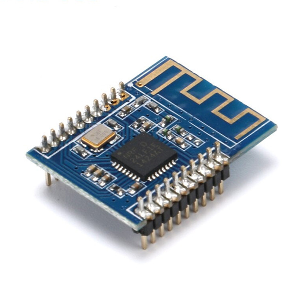
• Onboard 2.4G PCB antenna, ISM band, 1.27mm in-line, compact size for easy embedded applications.
• Supports six channels of data reception (one pair of six)
• Working method: half duplex
• Supports general modulation methods such as GFSK/FSK
• Supports 2Mbps/1Mbps/250Kbps data rate, and can set different transmit power
• Multi-frequency point: 126 frequency point, meeting the needs of multi-point communication and frequency hopping communication, 2400MHz~2525MHz, 1MHz frequency hopping stepping, channel switching time is about 130us
• Internally integrated high PSRR LDO
• Wide supply voltage: 1.9~3.6V, typical 3.3V
• Average emission current as low as 11.3mA (0dBm)
• Receive current: about 13mA@2Mbps
• Emission current: approx. 11 mA@0dBm
• Deep sleep: 0.5uA
• MCU current: 3.8mA@8MHzclock
• Built-in Enhanced ShockBurstTM baseband protocol engine
• Transceiver data hardware interrupt output
• Support 1bit RSSI output
• Operating temperature: -20 ° C ~ 60 ° C
• The best transmission distance: at an open rate of 2MBPS, up to about 50 meters
• Serves a set of power modes from ultra low power to a power-efficient active mode
Integrated SPI, IIC, UART, 6-12 bit ADC 14 channels, 2 PWM, Watchdog, on-chip oscillator, analog comparator, 3 timer/counters, random number generator, RTC, 18 interrupt sources
Precautions:
The wireless module is a static-sensitive device. Pay attention to the static electricity protection when using it. Especially in the dry winter, try not to remove the device on the touch module to avoid unnecessary damage.
The wireless module recommends using a DC power supply with a small ripple, and the operating voltage is recommended to operate at 3.3V.
The grounding of the module should be stable and reliable, and the ground wire should be as close as possible to the power supply. If you use a switching power supply, you must strengthen the retraction to avoid the ripple and spikes of the switching power supply affecting the operating characteristics of the module.
The module uses a PCB antenna. This antenna is easily affected by external circuits. When using it, please do not leave the line or place the device under and around the antenna. If possible, it is best to hollow out. The 2.4G frequency is relatively high, and various materials have certain influences. The general plastic has little effect. If there is a metal object, it will have a significant impact. In this case, it is recommended to use an SMA feeder to connect the SMA antenna.
| PIN |
PIN NAME |
PIN FUNCTIONS |
| 1 |
REST |
Reset |
| 2 |
P1.4 |
|
| 3 |
P1.3 |
|
| 4 |
P1.2 |
|
| 5 |
P1.1 |
|
| 6 |
P1.0 |
|
| 7 |
P0.7 |
|
| 8 |
P0.6 |
|
| 9 |
P0.5 |
|
| 10 |
P0.4 |
|
| 11 |
P0.3 |
|
| 12 |
PROG |
|
| 13 |
P0.2 |
|
| 14 |
P0.1 |
|
| 15 |
P0.0 |
|
| 16 |
P1.6 |
|
| 17 |
P1.5 |
|
| 18 |
VCC |
Power Input |
| 19,20 |
GND |
Power Ground |


 수량을 선택해주세요.