


 수량을 선택해주세요.


부하 스위치 모듈 -TPS22918
(SOLIDSWITCH CLICK)
개요
- 본 제품은 부하 스위치 모듈 -TPS22918 입니다.
- 4개의 싱글 채널 부하 스위치 TPS22918 칩을 기반으로 디자인된 제품입니다.
- 각 스위치는 N 채널 MOSFET을 가지고 있으며, 최대 5.5V까지의 입력 전압, 2A 까지 동작합니다.
- 각 스위치는 I2C 인터페이스를 가진 MAX7372 칩에 의해 on/off 입력 제어가 됩니다.
- 3.3V 시스템과 사용이 가능합니다.
특징
-
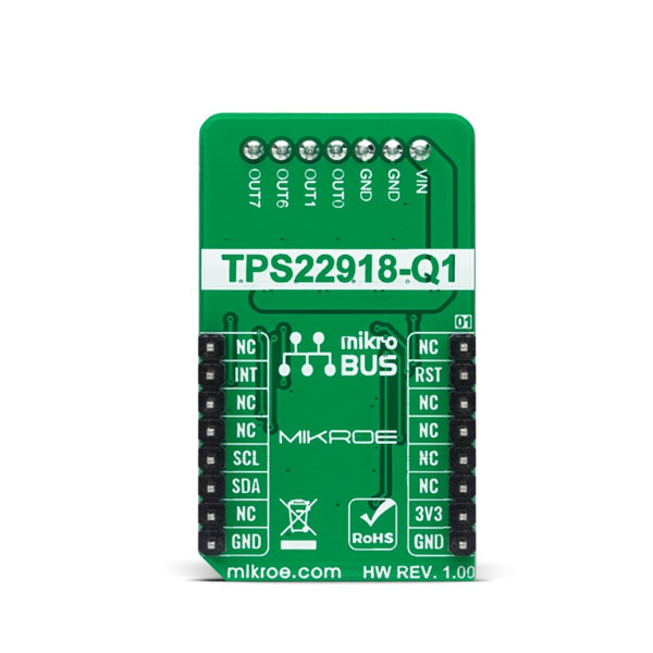
Type Relay Applications Can be used for industrial systems, set-top boxes, electronic point of scale, and various other applications. On-board modules TPS22918 - 5.5V 2A load switch from Texas Instruments Key Features Four integrated single channel load switches, flexible design, 2A maximum switch current, and more. Interface I2C Compatibility mikroBUS Click board size M (42.9 x 25.4 mm) Input Voltage 3.3V,External -
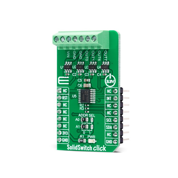
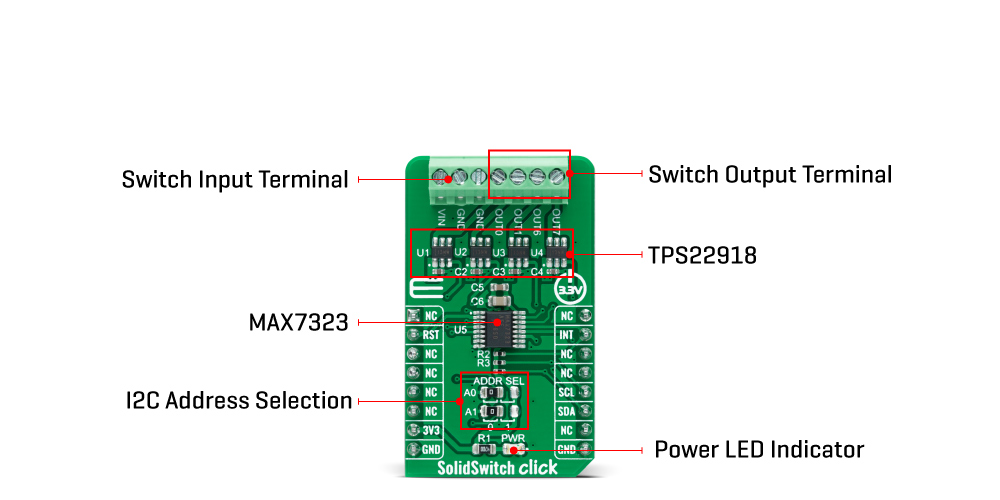
SolidSwitch Click, as its foundation, uses the TPS22918, a 5.5V 2A load switch from Texas Instruments. To reduce voltage drop for low voltage and high current rails, every TPS22918 implements a low resistance N-channel MOSFET, reducing the drop-out voltage across the device. An ON/OFF input on the ON pin of the TPS22918 controls the switches. The ON pin is compatible with the standard GPIO logic threshold and can be used with any MCU with 1V or higher GPIO voltage. That's why the control of all switches is established via the port expander, the MAX7323.
This Click board™ is designed to operate from an external supply voltage range from 1V to 5.5V. The TPS22918 works regardless of power sequencing order. The order in which voltages are applied to the VIN terminal and ON pin of the load switch will not damage the device as long as the voltages do not exceed the absolute maximum operating conditions.
SolidSwitch Click communicates with MCU through the MAX7323 port expander using the standard I2C 2-Wire interface with a frequency of up to 400kHz. It also has two address pins (A0 and A1) programmed by the user to determine the value of the last two LSBs of the slave address, selected by onboard SMD jumpers labeled as ADDR SEL to an appropriate position marked as 0 and 1, allowing selection of the slave address LSBs. Also, this Click board™ has a Reset pin, routed to the RST pin on the mikroBUS™ socket, which clears the serial interface in case of a bus lockup, terminating any serial transaction to or from the MAX7323.
Also, it uses an additional pin, the INT pin of the mikroBUS™ socket, which automatically flags data changes on any of the I/O ports of the MAX7323 used as inputs. The interrupt output INT and all transition flags are deasserted when the MAX7323 is accessed through the serial interface.
This Click board™ can be operated only with a 3.3V logic voltage level. The board must perform appropriate logic voltage level conversion before use with MCUs with different logic levels. However, the Click board™ comes equipped with a library containing functions and an example code that can be used, as a reference, for further development.


