


 수량을 선택해주세요.


AC 전압 센서 0-250V, 60Hz
(CE-VJ03-32MS2-0.5 AC Voltage Sensor 0-250V (60Hz))

개요
- 본 제품은 250VAC@60Hz를 측정할 수 있는 전압 센서입니다.
- 0-5V의 아날로그 전압 출력을 가지고 있으며, 12VDC로 동작합니다. 전압 출력은 측정된 값에 비례 하여 증가합니다.
- 본 제품은 스크류나 35mm DIN 레일에 쉽게 설치할 수 있으며, 터미널 블럭은 AWG#16 등급의 전선까지 삽입이 가능합니다.
- 아날로그 전압 입력을 가진 제품과 사용이 가능하며 센서 값을 전압으로 변환하는 공식은 아래와 같습니다.
-
Vrms = SensorValue * 0.25
특징
-
Product Specifications
Sensor Properties
Sensor Type Voltage (AC) Sensor Output Type Non-Ratiometric Input Voltage Min (AC) 0 V AC Input Voltage Max (AC) 250 V AC Measurement Error Max 0.5 % Input Frequency 60 Hz Sensor Response Time Max 300 ms
Electrical Properties
Supply Voltage Min 12 V DC Supply Voltage Max 12 V DC Current Consumption Max 15 mA Isolation Voltage (AC) 1.5 kV AC Output Voltage Min 0 V DC Output Voltage Max 5 V DC
Physical Properties
Recommended Wire Size 12 - 24 AWG Operating Temperature Min 0 °C Operating Temperature Max 50 °C -
Recommended Power Supplies
- 3024 – Power Supply 12VDC 2.0A (North American style plug)
- 3023 – Power Supply 12VDC 2.0A (European style plug)
- 3025 – Power Supply 12VDC 2.0A (UK style plug)
- 3022 – Power Supply 12VDC 2.0A (Australian style plug)
In order to use one of these power supplies with this sensor, you must cut the small plug from the end of the power supply and connect the wires directly into the sensor. You can also use a 3031 – Female Pigtail.
-
Mounting Suggestion
Warning: The AC Voltage Sensor needs to be attached in parallel with the line voltage. This requires cutting and using loose ends of high power cables. ALWAYS be sure to turn off the power running through the cables while manipulating and before cutting the cables. When attaching the cables, be sure to follow your country's wiring code to ensure safe installment of the sensors and to reduce the risk of injury and fire. If you are uncomfortable, consult with a certified electrician.

-
Connection
This sensor connects to any device with an Analog Input.You can use the 1144 - 12V Sensor Adapter to connect the voltage sensor to an analog input as pictured below.

- Connect the +12V terminal on the 1144 to the voltage sensor terminal 5 (+12V).
- Connect the GND terminal on the 1144 to the voltage sensor terminal 6 (-).
- Connect the ANLG terminal on the 1144 to the voltage sensor terminal 8 (+).
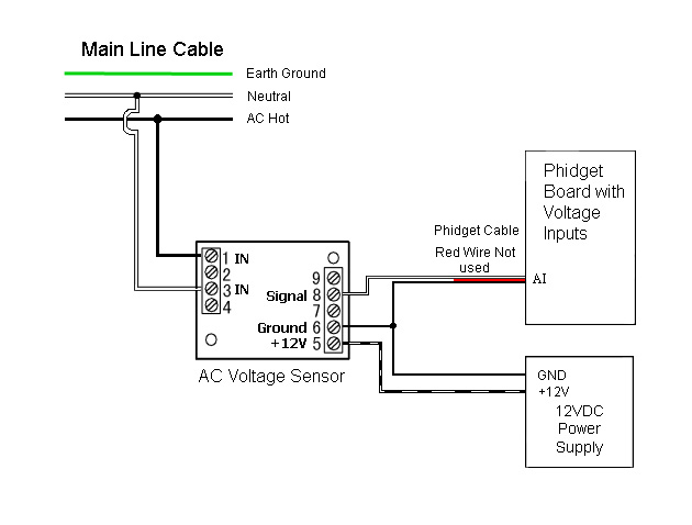
Alternatively, you can use the 3002 - Sensor Cable 60cm or the3004 - Sensor Cable 350cm to connect the AC Voltage Sensor to your Phidget. Just snip off the connector from one end of the sensor cable and connect the wires as described below. You can also use a3031 – Female Pigtail if you don't want to cut the barrel jack off of the power supply.
- Connect the Power Supply +12V wire (the wire with the white line) to the voltage sensor terminal 5 (+12V).
- Connect the Power Supply Ground wire and the Analog Sensor Cable Black wire to the voltage sensor terminal 6 (-).
- Connect the sensor cable white wire to the voltage sensor terminal 8 (+).
- Connect the AC main wires to the voltage sensor terminals 1 (IN) and 3 (IN).

For boards that have power input, such as the 1019 or the 1073, if the supplied power is 12V, then the + terminal block on the Phidget Board can be connected to the voltage sensor terminal 5 (+12V), and the G terminal block on the Phidget Board can be connected to the sensor terminal 6 (-).
-


