


 수량을 선택해주세요.


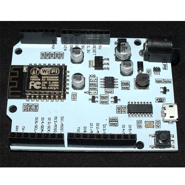
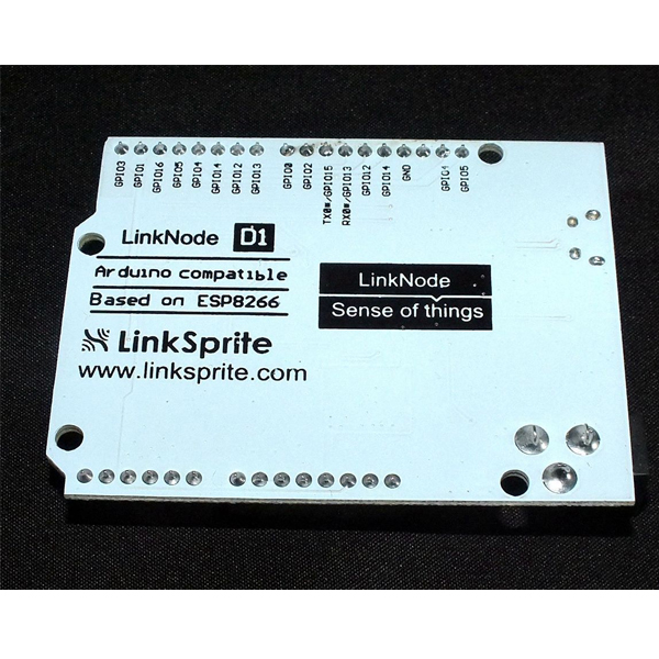
링크노드 D1 -ESP8266 WiFi 아두이노 호환 개발보드
(LinkNode D1
-ESP8266 WiFi Arduino Compatible Board)
개요
- LinkNode D1은 아두이노 호환 WiFi 개발보드입니다.
- ESP-8266EX WiFi 컨트롤러를 탑재하고 있는 제품으로 아두이노 IDE를 이용하여 프로그래밍이 가능합니다.
- 또한 아두이노 호환 핀 레이아웃을 가지고 있어 아두이노용 쉴드의 사용이 가능합니다.
특징
- Powered by ESP-8266EX
- 11 Digital I/O pins
- 1 Analog Input pin
- 1 micro USB port for power/configure
- Power jack for 9-24V power input
- Compatible with Arduino programming
- Compatible with NodeMCU
- OTA -- Wireless Upload(Program)
-
Pin Mapping


문서
-
Tutorials
1. Get started in Arduino
If you have used Arduino before, you will feel that the LinkNode D1 is as same as Arduino, and there is no difference between their programming. The only limitation of LinkNode D1 is that it only has 11 digital ports and 1 analog input port.
a. Requirements
- Arduino IDE, (the latest version is 1.6.8 )
- The Arduino core for LinkNode D1
b. Manually install hardware package(Option 1)
- Install Arduino IDE
- Manually download hardware package from github
- Click the button Download ZIP to download
- Go to installation directory of Arduino IDE, and create a esp8266com directory
- Move the unzipped LinkNodeD1 file to ESP8266com
c. Use git to install (Option 2)
- You can use git command to download the hardware package like:
cd <ArduinoIDE path>/hardware mkdir esp8266com cd esp8266com git clone https://github.com/pcduino/LinkNodeD1
d. Download binary tools (you need Python 2.7)
cd esp8266/tools python get.py
e. Check the configuration of Board
- Open Arduino IDE and go to Tools --> Board --> LinkNode D1
- Choose your own configuration
Upload Using
- Serial – Use USB port on board to upload flash
- OTA – Use OTA to upload flash
CPU Frequency
- 80MHz
- 160MHz
Flash Size
- 4M (3M SPIFFS) – 3M File system size
- 4M (1M SPIFFS) – 1M File system size
Upload Speed
- 921600 bps – recommend
f. Create a Arduino Project
- Connect LinkNode D1 to your PC
- Check your serial port which your PC recognize

- Enter the following source code and click the Upload button
void setup() { // initialize digital pin GPIO2/D9 as an output. pinMode(BUILTIN_LED, OUTPUT); } // the loop function runs over and over again forever void loop() { digitalWrite(BUILTIN_LED, HIGH); // turn the LED on (HIGH is the voltage level) delay(1000); // wait for a second digitalWrite(BUILTIN_LED, LOW); // turn the LED off by making the voltage LOW delay(1000); // wait for a second }- After finish uploading, please check the BLUE LED on the ESP-8266EX chip, is it blinking?
2. Hello World
- Take the steps above and run the following code:
void setup() { Serial.begin(115200); } // the loop function runs over and over again forever void loop() { Serial.println("Hello world!"); delay(1000); // wait for a second }- After finish uploading, and open the Serial Monitor in Arduino IDE
- The serial will print Hello world! in every second.
3. Use I/O expander shield with LinkNode D1

I/O Expander shield is a shield used to expand the number of I/Os of Arduino. It is based on the chipset MCP23017. The chipset MCP23017 communicates with Arduino Uno through I2C interface. It adds GPIOA and GPIOB, a total of 16 I/Os.
- Mount the expander shield to LinkNode D1
- Program the source code to the board
#include <Wire.h> const byte mcp_address=0x20; // I2C Address of MCP23017 Chip const byte GPIOA=0x12; // Register Address of Port A const byte GPIOB=0x13; // Register Address of Port B const byte IODIRA=0x00; // IODIRA register const byte IODIRB=0x01; // IODIRB register void setup() { //Send settings to MCP device Wire.begin(); // join i2c bus (address optional for master) Wire.beginTransmission(mcp_address); Wire.write((byte)IODIRA); // IODIRA register Wire.write((byte)0x03); // set GPIOA-0/GPIOA-1 to inputs Wire.endTransmission(); } void loop() { Wire.beginTransmission(mcp_address); Wire.write((byte)GPIOA); // set MCP23017 memory pointer to GPIOB address Wire.endTransmission(); Wire.requestFrom(0x20, 1); // request one byte of data from MCP20317 int inputs=Wire.read(); // store the incoming byte into "inputs" if((inputs&0x01)==0) { Wire.beginTransmission(mcp_address); Wire.write(GPIOA); // address bank A Wire.write((byte)0x04); // value to send GPIOA-2 HIGH Wire.endTransmission(); } if((inputs&0x02)==0) { Wire.beginTransmission(mcp_address); Wire.write(GPIOA); // address bank A Wire.write((byte)0x08); // value to send GPIOA-3 HIGH Wire.endTransmission(); } else { Wire.beginTransmission(mcp_address); Wire.write(GPIOA); // address bank A Wire.write((byte)0x00); // value to send GPIOA LOW Wire.endTransmission(); } }- Set all 4-bit DIP jumpers to ON
- Press the button S1 and S2 respectively.
- Press S1, L1 (RED) will turn on.
- Press S2, L2 (GREEN) will turn on.
4. WiFi Manager
The ESP8266 WiFi Connection manager with web captive portal, this Arduino library can make configure AP's SSID and password via web page when you want LinkNode D1 to connect to AP.
- Open Arduino IDE and go to Sketch --> Include Library --> Manage Libraries
- Search the wifimanager and install it

- Program the following source code:
#include <ESP8266WiFi.h> //https://github.com/esp8266/Arduino //needed for library #include <DNSServer.h> #include <ESP8266WebServer.h> #include <WiFiManager.h> //https://github.com/tzapu/WiFiManager void setup() { // put your setup code here, to run once: Serial.begin(115200); //WiFiManager //Local intialization. Once its business is done, there is no need to keep it around WiFiManager wifiManager; //reset saved settings //wifiManager.resetSettings(); //set custom ip for portal wifiManager.setAPStaticIPConfig(IPAddress(10,0,1,1), IPAddress(10,0,1,1), IPAddress(255,255,255,0)); //fetches ssid and pass from eeprom and tries to connect //if it does not connect it starts an access point with the specified name //here "AutoConnectAP" //and goes into a blocking loop awaiting configuration wifiManager.autoConnect("LinkNodeAP"); //or use this for auto generated name ESP + ChipID //wifiManager.autoConnect(); //if you get here you have connected to the WiFi Serial.println("connected... :)"); } void loop() { // put your main code here, to run repeatedly: }- After upload the program, the LinkNode D1 will create a AP called LinkNodeAP
- Use your mobile phone to connect this AP
- Open a browser and enter the ip address 10.0.1.1 and you will see the following website:

- Click the button configure WiFi
- Select your WiFi AP which you want to connect and enter your wifi password.
- If connecting failed, you can go to the same website to configure it again.
- Also, you can use Serial Monitor in Arduino IDE to check the status.
5. Connect to LinkSprite IO
LinkSprite IO is an IoT platform which supports RESTful API and WebSocket. These make the mobile APP, website application or device connect it very easily. The following I will introduce is about how to use LinkNode D1 to communicate with LinkSprite IO platform.
a. Create a new account and device on LinkSprite.io
- Go to www.linksprite.io and sign up
- Enter your Email and password to create a new account
- Go to My Account to get your own API Key. The API Key is fatal because only add the Key in your codes, can the data sync to your IoTgo account.

- Click My Device, and choose Create DIY Device.

- Click the created device icon and get the DeviceID.

b. Update the source code using your own apikey and device ID
Device API which the LinkSprite IO support is JSON-based, which means all request and response data is enclosed in JSON format. Currently it supports 3 kind of request.
- Update: Update device status to LinkSprite IO
- Query: Get device status from LinkSprite IO
This demo will send http POST request to query the param--light on linksprite.io, if the light is on, then turn the LED, if off, then turn off the LED.
#include <ESP8266WiFi.h> #include <WString.h> //the library are needed for autoconfig WiFi #include <DNSServer.h> #include <ESP8266WebServer.h> #include <WiFiManager.h> // replace with your own API key and device ID, String apikey = "xxxxxxxxxxxxxxxxxxxxxxxxxxxx"; const char* deviceID="xxxxxxxxxxxxx"; const char* server = "www.linksprite.io"; WiFiClient client; void setup() { Serial.begin(115200); pinMode(BUILTIN_LED, OUTPUT); WiFiManager wifiManager; wifiManager.setAPStaticIPConfig(IPAddress(10,0,1,1), IPAddress(10,0,1,1), IPAddress(255,255,255,0)); wifiManager.autoConnect("LinkNodeAP"); Serial.print("WiFi Connected ...\n"); Serial.println("WiFi connected"); } void loop() { if (client.connect(server,80)) { String postStr ="{"; postStr +=""action":"query","; postStr +=""apikey":""; postStr += apikey; postStr +="","; postStr +=""deviceid":""; postStr += deviceID; postStr +="","; postStr += ""params":"; postStr += "["; postStr += ""light""; postStr +="]"; postStr +="}"; client.print("POST /api/http HTTP/1.1\n"); client.print("Host: "); client.print(server); client.print("\nContent-Type: application/json\n"); client.print("Content-Length: "); client.print(postStr.length()); client.print("\n\n"); client.print(postStr); } delay(1000); Serial.println("Store response..."); String request = ""; while (client.available()) { char c = client.read(); request +=c; } if (request!= NULL) { int index1 = request.indexOf(":{"); int index2 = request.indexOf("},"); String param = request.substring(index1, index2 + 1); Serial.print("The param is "); Serial.println(param); if(param.indexOf("off")>0){ digitalWrite(BUILTIN_LED, HIGH); Serial.println("OFF"); } else if(param.indexOf("on")>0){ digitalWrite(BUILTIN_LED, LOW); Serial.println("ON"); } client.stop(); Serial.println("Waiting..."); delay(2000); } }
``` #### c. Test- Program the source code and open the Serial monitor to check the status

- Open your light device which is create on linksprite.io
- Click the button ON and OFF
- Check the status of LED on LinkNode D1, is it following your control?
Type a description for this product here...


연관제품
- 연관제품 1


