


 수량을 선택해주세요.


배터리 충전/벅-부스트 전련관리 모듈 -MAX77654
(BATT-MAN 2 CLICK)
개요
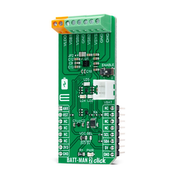
- 본 제품은 배터리 충전/벅-부스트 전련관리 모듈 -MAX77654 입니다.
- MAX77654 칩을 장착하고 있으며, I2C 인터페이스를 가지고 있습니다.
- 3개의 벅-부스트 레귤레이터, 1개의 LDO 출력, 리튬배터리 충전할 수 있는 포트를 지원합니다.
특징
-
HOW DOES IT WORK?
BATT-MAN 2 Click as its foundation uses the MAX77654, a highly-integrated battery charging and power management solution for low-power applications from Analog Devices. It features a single-inductor, multiple-output (SIMO) buck-boost regulator efficiently that provides three independently programmable power rails available on onboard terminals labeled as VSB0, VSB1, and VSB2. Also, it has one 100mA LDO output, labeled as VLDO, with ripple rejection for audio and other noise-sensitive applications. This LDO output can also be configured as a load switch to manage power consumption by disconnecting external blocks when not required. The LDO output can be activated/deactivated by populating the JP2 onboard jumper.
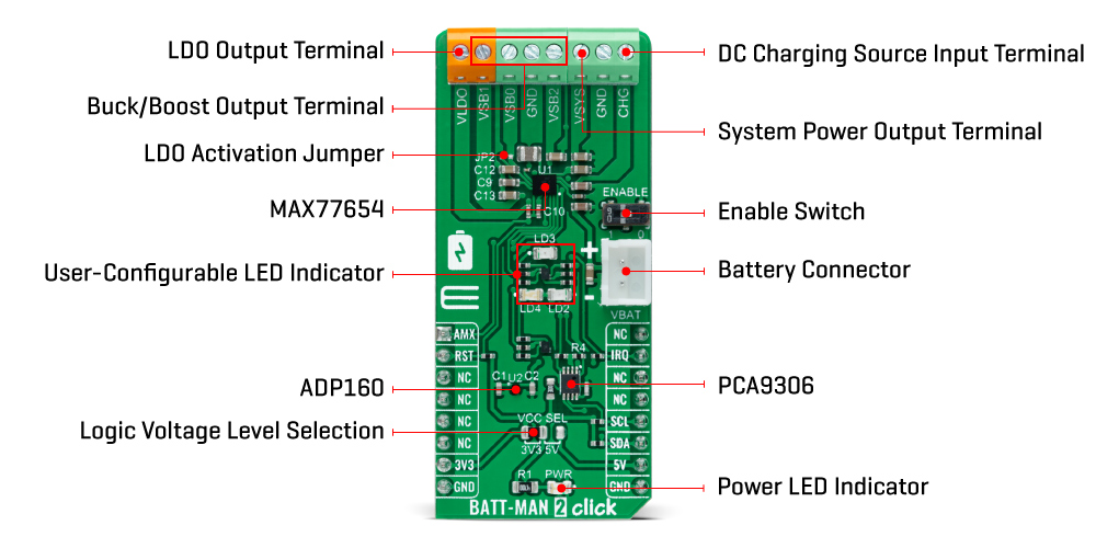
The MAX77654 also has an integrated highly-configurable linear charger that supports a wide range of Li+ battery capacities with a wide range of charge current and charger termination voltage options, featuring battery temperature monitoring for additional safety (JEITA). The charger feature is OFF when the CHG supply is invalid (supply in the range from 4.1V up to 7.25V), disabled, or with the fresh battery. In addition to all the output terminals on this board, another one is marked with VSYS, which is the system power output terminal. In addition to providing power to the system resources and the control logic of the device, VSYS is also designed for external use.
BATT-MAN 2 Click communicates with MCU using the standard I2C 2-Wire interface for configuring and checking the device's status. Since the sensor for operation requires a 1.8V logic voltage level to work correctly, a small regulating LDO is used, the ADP160 from Analog Devices, providing a 1.8V out of mikroBUS™ rails. That's why the PCA9306 voltage-level translator is also featured. The I2C interface bus lines are routed to the dual bidirectional voltage-level translator, allowing this Click board™ to work with both 3.3V and 5V MCUs properly.
An onboard switch labeled as ENABLE has the primary purpose of generating a wake-up signal for the PMIC that turns ON the regulators by setting the switch to an appropriate position marked as 1 or 0. In addition, this Click board™ also has some additional features, such as a Reset routed to the RST pin on the mikroBUS™ socket used to hold the processor in a Reset state when the device is powered down.
It also uses an interrupt pin, the INT pin of the mikroBUS™ socket, to signal an essential change in device status, while the three additional LED indicators, red, yellow, and blue LEDs labeled as LED2, LED3, and LED4, can be used for optional user-configurable visual indication. Besides, this device includes an analog multiplexer (AMX), routed to the AN pin on the mikroBUS™ socket, that switches several internal voltage and current signals to an external node for monitoring with an external ADC.
This Click board™ can operate with both 3.3V and 5V logic voltage levels selected via the VCC SEL jumper. This way, it is allowed for both 3.3V and 5V capable MCUs to use the communication lines properly. However, the Click board™ comes equipped with a library containing easy-to-use functions and an example code that can be used, as a reference, for further development.
-
Type Buck-Boost Applications Can be used as a battery charging and power supply solution for low-power applications where size and efficiency are critical On-board modules MAX77654 - single inductor, multiple-output (SIMO) power management IC (PMIC) from Maxim Integrated, now part of Analog Devices Key Features 3 x Buck-Boost outputs, 1 x LDO output, low power consumption, DC charging source, charger optimized for small battery size, flexible and configurable interface, analog MUX output for power monitoring, and more Interface I2C Compatibility mikroBUS Click board size L (57.15 x 25.4 mm) Input Voltage 3.3V or 5V,External


