


 수량을 선택해주세요.


4채널 DC-DC 스텝다운 모듈 -MPM54304
(STEP DOWN 6 CLICK)
개요
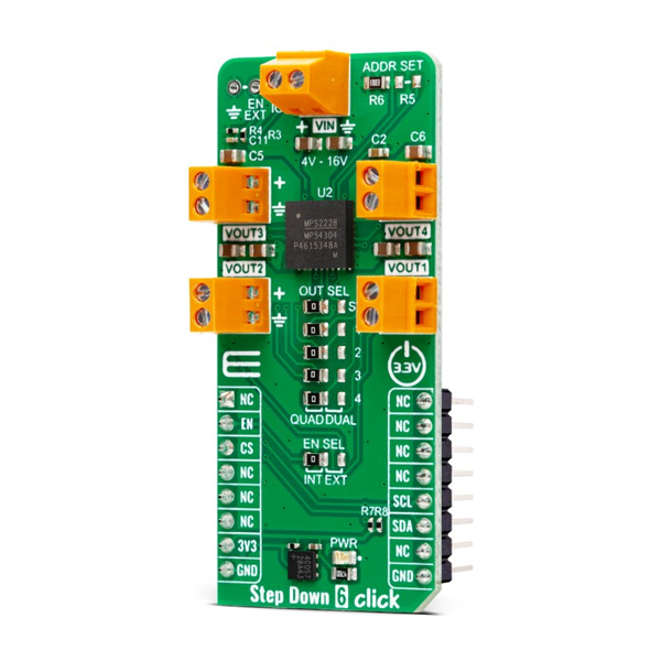
- 본 제품은 4채널 DC-DC 스텝다운 모듈 -MPM54304입니다.
- 4채널 출력 DC/DC 스텝다운 MPM54304 칩을 장착하고 있으며, 1/2채널은 최대 3A, 3/4채널은 최대 2A까지 전달이 가능합니다.
특징
-
HOW DOES IT WORK?
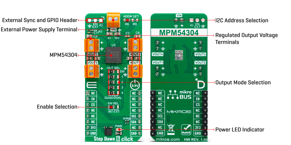
Step Down 6 Click is based on the MPM54304, a quad-output power module from Monolithic Power Systems (MPS). This IC operates over a 4V to 16V input voltage range that can be supplied over the VIN screw terminal. It can step down input voltages as output voltages from 0.55V to 5.4V. The user can choose between straight or parallel output depending on the used output channels, from VOUT1 to VOUT4. Channels VOUT1 and VOUT2 can be paralleled to provide up to 6A of current, and channels VOUT3 and VOUT4 can be paralleled to provide up to 4A of current. The selection between quad and dual channel outputs can be set via the OUT SEL jumpers, where QUAD is selected by default. The user must set all five jumpers into the proper position for the output to work correctly.
The MPM54304 has internal auto-compensation, which eliminates the need for an external compensation network, employs a constant-on-time (COT) control scheme to provide ultra-fast load transient responses, and minimizes the required output capacitance. It also features a two-time non-volatile programmable memory for storing register settings. Using the host MCU, users can set switching frequency, output voltage, over-current and over-voltage protection thresholds, power-on, power-off sequencing, and Forced PWM or Auto-PWM/PFM.
Step Down 6 Click uses a standard 2-Wire I2C interface to communicate with the host MCU, supporting clock frequency up to 3.4MHz and ADDR SET jumper to set the I2C address. In addition to being enabled via the EN pin of the mikroBUS™ socket, the MPM54304 can also be enabled with the appearance of an external power supply by setting the EN SEL jumper to the appropriate position. For that to be done, the EN SEL jumper must be set to the EXT position, thus losing the enable function over the EN pin of the mikroBUS™ socket.
The ADDR SET jumper actually uses the GPIO pin of the MPM54304, which can also be used for other purposes, as it is an input/output pin. This pin can be configured as a Power-Good (PG) pin over the unpopulated IO header that will go to a LOW logic state if any enabled regulator falls below the under-voltage threshold or when all regulators are disabled. It can also be used in the Output Port mode, where it will output corresponding logic depending on the related register. Finally, it can also be used in the SYNCO mode, where it will become the sync output allowing users to phase-shift the clock output to sync another device's switching frequency.
This Click board™ can be operated only with a 3.3V logic voltage level. The board must perform appropriate logic voltage level conversion before using MCUs with different logic levels. Also, it comes equipped with a library containing functions and an example code that can be used, as a reference, for further development.
SPECIFICATIONS
Type Buck Applications Can be used for the development of FPGA power supplies, multi-rail power systems, MCU/DSP power supplies, and more On-board modules MPM54304 - quad-output power module from Monolithic Power Systems (MPS) Key Features Wide operating range, wide output range, straight and parallel continuous current output, interleaved operation, configurable multi-functional GPIO pin, configurable paralleling, switching frequency, output voltage, over-current, and over-voltage thresholds, power-on and power-off sequencing, Forced PWM or Auto-PWM/PFM, and more Interface I2C ClickID Yes Compatibility mikroBUS Click board size L (57.15 x 25.4 mm) Input Voltage 3.3V,External


