


 수량을 선택해주세요.


4채널 시간 인터벌 측정 모듈 -AS6500, SPI
(TDC 2 CLICK)

개요
- 본 제품은 4채널 시간 인터벌 측정 모듈 -AS6500, SPI 입니다.
- AS6500칩을 기반으로 디자인된 제품으로 시간 인터벌을 측정할 수 있습니다.
- ToF 레이저 거리 측정센서, 물체 검출 등의 어플리케이션에 사용할 수 있습니다.
특징
-
HOW DOES IT WORK?
TDC 2 Click is based on the AS6500, a high-resolution time-to-digital converter from ScioSense, featuring CMOS inputs, high measurement performance, and high data throughput. The AS6500 can measure time intervals as low as 5ns with 10ps resolution on all four STOP channels at a sampling rate of up to 1.5Ms/s. It is characterized by high configuration flexibility, a wide measurement range from 0 to 16s, and simple data post-processing thanks to calibrated results. It calculates calibrated stop measurements referenced to the applied reference clock. This Click board™ is ideal for optical applications, including general-purpose laser distance measurement in 1D, 2D, and 3D, speed control, object recognition, time-of-flight spectroscopy, and many more.
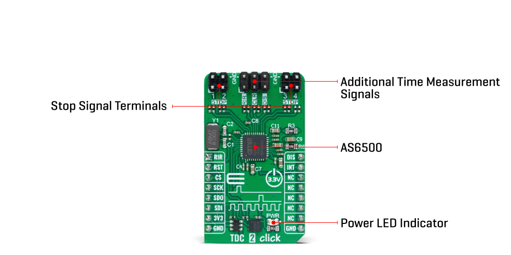
The positive edges of the stop signals, applied on the STOP terminals (1-4), are measured versus the preceding reference clock edge. The reference clock can be brought externally via the CLR pin on the middle header terminal or from the onboard 8MHz quartz oscillator. This feature is selectable through software – register-setting. The reference clock represents the framework for all time measurements and serves as a universal time base. The clock pulses are measured continuously by the TDC as a time reference point for STOP pulses and as an internal reference period. The measurement of the STOP events always refers to the preceding reference clock. Additionally, the reference clock is counted continuously, and the actual count is assigned as a reference index to a STOP pulse.
TDC 2 Click communicates with the host MCU through a standard SPI interface to read data and configure the frontend, supporting high clock speed up to 50MHz and the most common SPI mode, SPI Mode 1. Along with SPI pins, it also uses an interrupt pin that indicates to the host MCU that data are available and ready for processing.
The AS6500 uses a few more signals available on the mikroBUS™ socket for successful time measurements. With the RIR pin, the internal counter for the reference index is set back to zero, simplifying the overview of the reference index in the output data stream. Next, setting the disable pin, marked as DIS, to a high logic state, the measurements on all four stops are disabled. On the other hand, the reference clock is not affected, and internal reference measurements are continued. Apart from the mikroBUS™ socket, these signals can also be found on the middle header, grouped with the reference clock pin.
This Click board™ can only be operated from a 3.3V logic voltage level. Therefore, the board must perform appropriate logic voltage conversion before using MCUs with different logic levels. However, the Click board™ comes equipped with a library containing functions and an example code that can be used as a reference for further development.
SPECIFICATIONS
Type Clock generator Applications Can be used general-purpose laser distance measurement in 1D, 2D, and 3D, speed control, object recognition, time-of-flight spectroscopy, and more On-board modules AS6500 - time-to-digital converter from ScioSense Key Features Simple data post-processing, high measurement performance, SPI serial interface, high data throughput, high configuration flexibility, unlimited measurement range, high resolution, and more Interface SPI Compatibility mikroBUS Click board size M (42.9 x 25.4 mm) Input Voltage 3.3V


