


 수량을 선택해주세요.


CAN/CAN FD 통신 모듈 -TCAN4550
(CAN FD 6 CLICK)
개요
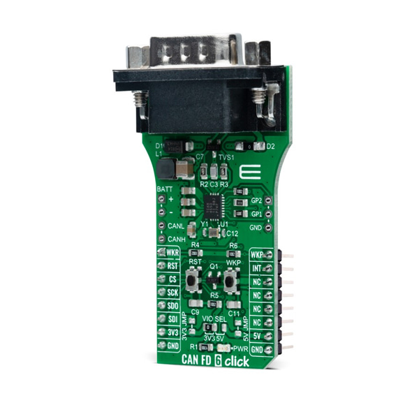
- 본 제품은 CAN/CAN FD 통신 모듈 -TCAN4550입니다.
- TCAN4550 CAN 컨트롤러 칩을 기반으로 디자인된 제품으로 SPI 인터페이스를 가집니다.
- 3.3V나 5V와 사용이 가능합니다.
특징
-
Type CAN Applications Can be used for high-speed CAN networks in automotive and industrial applications, especially where low-power mode with wake-up capability via the CAN bus is required. On-board modules TCAN4550 - CAN FD controller that provides an interface between the CAN bus and the CAN protocol controller up to 5Mbps from Texas Instruments Key Features Low power consumption, classic CAN backwards compatible, wide operating range, optimized behavior when unpowered, high-bandwidth, data-rate flexibility, and more. Interface SPI Compatibility mikroBUS Click board size L (57.15 x 25.4 mm) Input Voltage 3.3V or 5V,External -
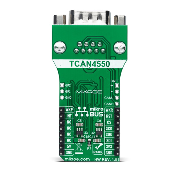
CAN FD 6 Click as its foundation uses the TCAN4550, a CAN transceiver that supports CAN and CAN FD protocols and provides an interface between the CAN bus and the CAN protocol controller up to 5 megabits per second (Mbps) from Texas Instruments. It is characterized by high-bandwidth and data-rate flexibility, provides an SPI interface between the CAN bus and the system processor, and supports wake-up features local and bus wake using the CAN bus. The device includes many protection features providing CAN bus robustness, including fail-safe mode, internal dominant state timeout, and wide bus operating range.
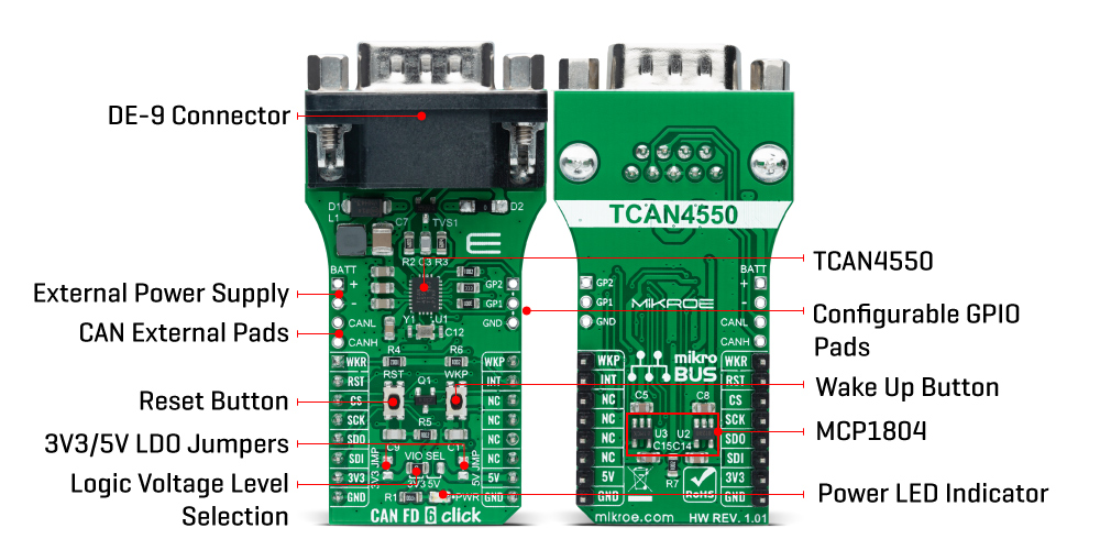
The TCAN4550 has one pin used for waking up the device from Sleep mode. This pin is connected to an external button labeled as WAKE and the PWM pin of the mikroBUS™ socket labeled as WKP to generate a local Wake-Up function. A Wake-Up event on the CAN bus switches the inhibit output pin INH to the high level. The INH pin provides an internal switch towards the battery supply voltage and control external voltage regulators, the MCP1804 from Microchip. Through SMD jumpers labeled as 3V3JMP and 5VJMP, the LDOs output voltages can be used to power up the mikroBUS™ 3.3V and 5V power rails. However, it should be noted that Mikroe does not advise powering up their systems this way. That is why these jumpers are left unpopulated by default.
CAN FD 6 Click communicates with MCU using a standard SPI interface supporting clock rates up to 18MHz to transmit and reception CAN frames. With an additional 40MHz crystal, the TCAN4550 can meet CAN FD rates up to 5 Mbps data rates to support higher data throughput and operates from a 6V to 24V external power supply header on the board's right side. This feature makes the TCAN4550 device ideal for many different applications, including those in the automotive market.
This Click board™ comes equipped with the industry-standard DB-9 connector, making interfacing with the CAN bus simple and easy. Besides, the user can connect the CAN signals directly through the CAN External header located on the board's left edge.
In addition to these features, the TCAN4550 also uses several GPIO pins connected to the mikroBUS™ socket. The RST pin the mikroBUS™ can perform the Hardware Reset function, which resets the device to the default settings and puts it into standby mode. This feature can also be achieved through the onboard push-button labeled as RST. Next to these pins, the ATA6571 uses the WKR pin as a dedicated wake-up request pin from a bus wake request and INT pin as an interrupt feature routed on the AN and INT pin of the mikroBUS™ socket. For interrupt purposes, the user can also use GPIO pins from the header positioned on the board's right side.
This Click board™ can operate with both 3.3V and 5V logic voltage levels selected via the VIO SEL jumper. It allows for both 3.3V and 5V capable MCUs to use the UART communication lines properly. However, the Click board™ comes equipped with a library containing easy-to-use functions and an example code that can be used, as a reference, for further development.


