


 수량을 선택해주세요.


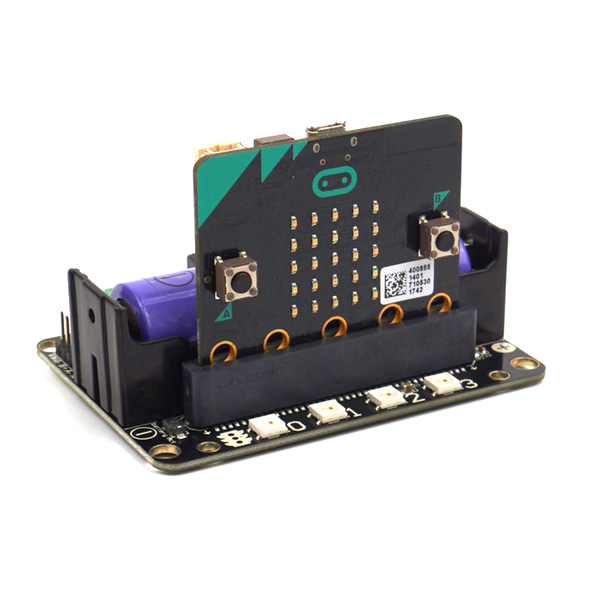
micro:bit용으로 Robotbit 로봇 확장 보드
(RobotBit - Robot Expansion Board for Micro:bit)
개요
- 본 제품은 micro:bit용으로 디자인된 Robotbit 로봇 확장 보드입니다
- DC 모터, 스텝 모터, 서보를 동작시킬 수 있으며, 보드상의 버저, RGB LED 픽셀을 장착하였습니다.
- micro:bit의 모든 IO를 접근할 수 있게 디자인되었습니다.
- 18650 배터리 홀더, 내장된 리튬 배터리 부스트, 충전, 보호 칩을 장착하고 있습니다.
- 외부 전원입력을 지원합니다.
- 학생들에 로봇의 기초를 가르치기에 적합한 제품입니다.
특징
-
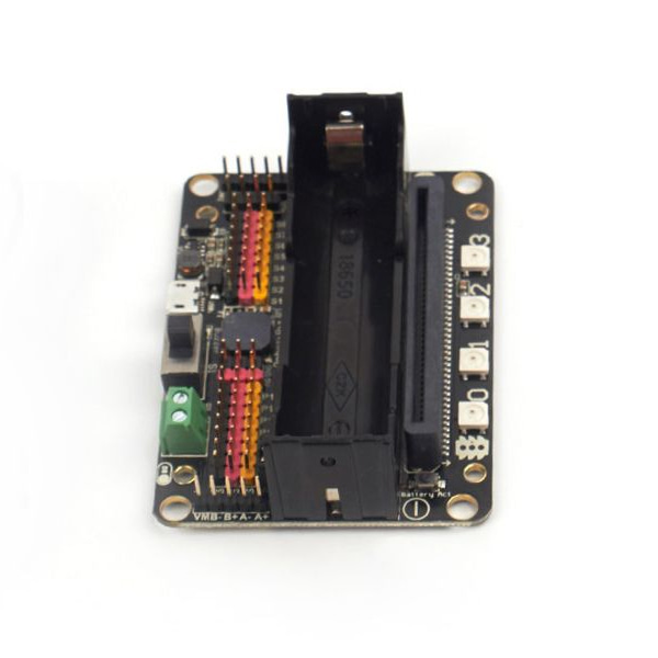
Hardware interface
1. 5V external power input(with anti-reverse protection)
2. Power switch
3. Power Indicator
4. Battery Indicator
5. Micro USB charing port
6. 4-channel DC motor / 2-channel stepper motor
7. Jumper for buzzer selection
8. 8 channel IO(corresponding to Micro:bit P0-P2、P8、P12-P15)
9. 5V and GND port
10. Buzzer
11. 8 channel servo port
12. I2C interface (expandable I2C module)
13. 18650 battery case
14. Bettery protection recovery push button
15. Micro:bit edge connector
16. 4x RGB pixel - 17. Servo driver (PCA9685)
18. 2xDc/Stepper driver (DRV8833)
19. KittenBot robot chassis mounting hole
20. Standard LEGO hole -
Supported software
Available Coding platform: Kittenblock(based on Scratch3.0) or Makecode and python(Mu editor in microbit mode)
문서
-
Robotbit Quick start
Put the 18650 battery on the Robotbit, pay attention to the positive and negative pole.
Plug the Microbit into the Robotbit and pay attention to the plugging direction.
Click the battery activation button
Turn on the 18650 battery switch
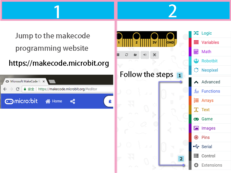
Open the makecode editor ( http://makecode.microbit.org ) and press add package.
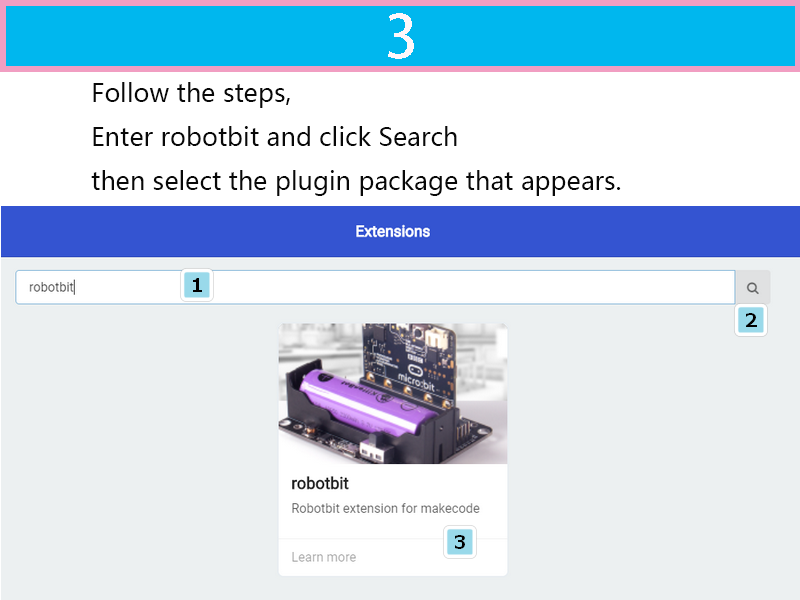
Search robotbit
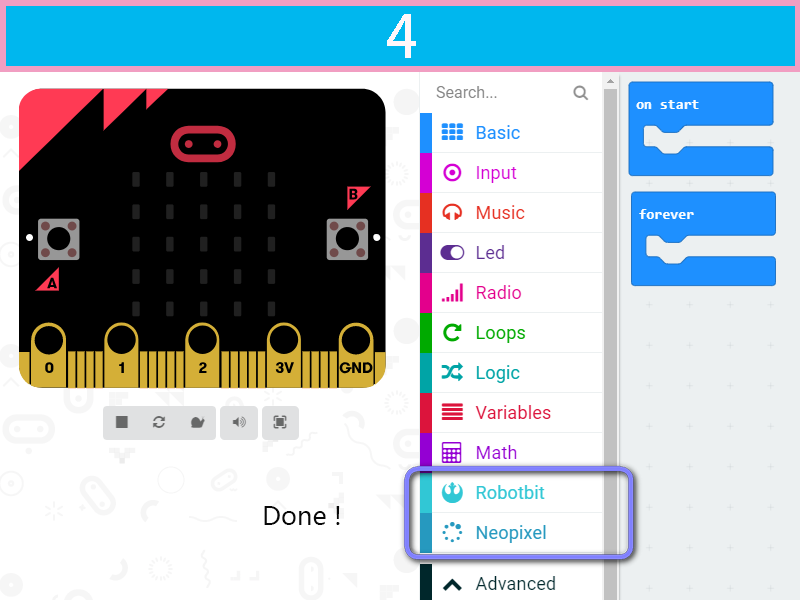
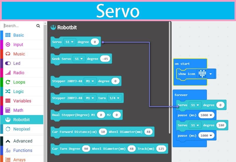
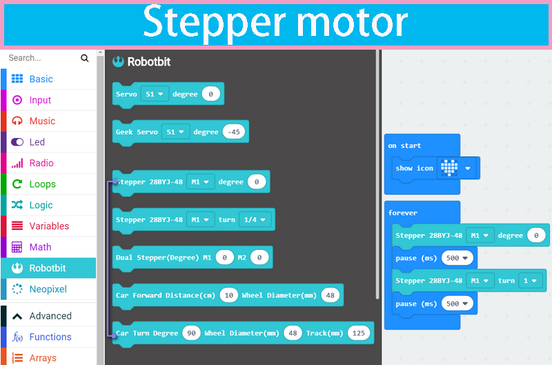
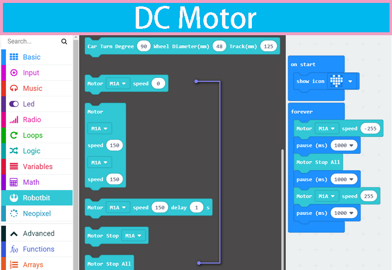
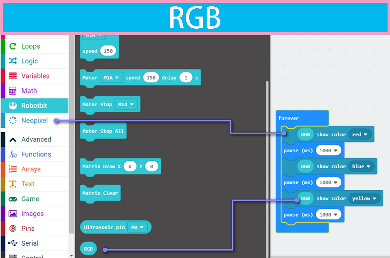
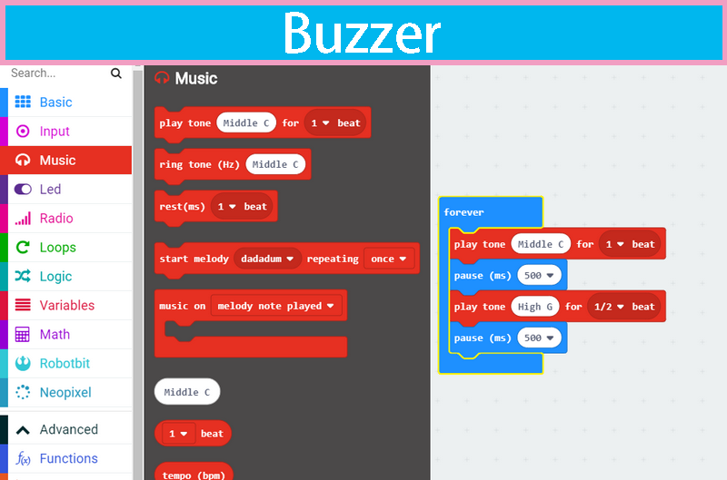
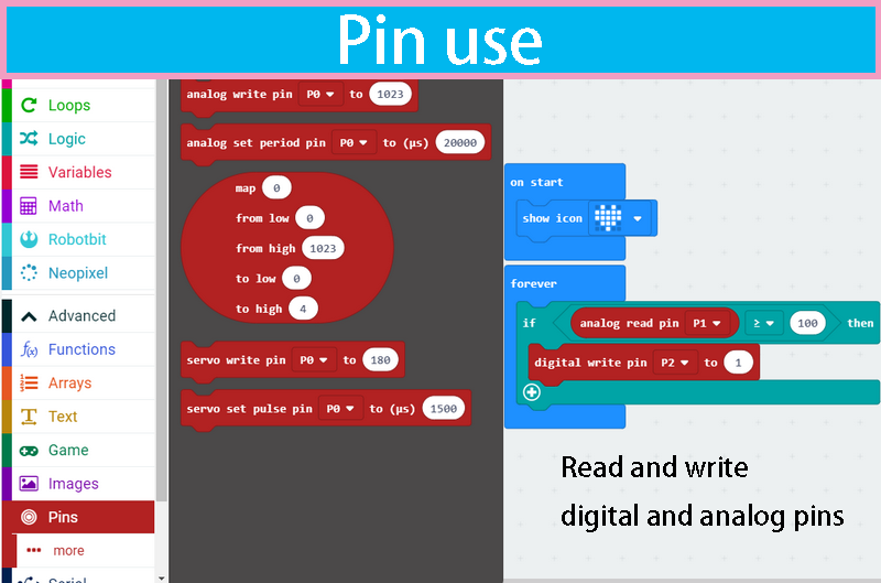
Drag some of the robotbit blocks out to workspace, remember to connect the corresponding motor servos, etc.
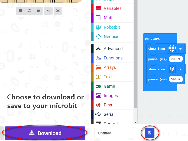
Before downloading, remember to connect to Microbit's with a micro usb cable and click the download button.
After click download button, a file save box will prompt, please choose to save it to the Microbit removable disk.
the final effect of the code block in the diagram above
F&Q
The battery is plugged in, there is no response after turn on switch?
Check if the battery activation button has been pressed? Check if the battery is positive or negative? Check if the battery has power?
What is the battery activation button used for?
In the case of overcurrent, or short circuit, or switch battery cell, the battery protection chip will protect the the circuit. Click the battery activation button to resume normal working mode.
Pluged in usb cable and I can't find Microbit
The usb on the robotbit can only be used for charging. It can't be used to download the program. It is plugged into the usb port of the robotbit. The computer will not respond.
Will it smoke if I insert battery inverse?
No, the robotbit design is anti-reverse protect in consideration of general miss operations. Inversely plug in will just not output power.
Will Microbit damage if plug in face back?
No, it will just refuse to work.
P0 pin control does not respond? Is it broken?
You need to unplug the buzzer selection jumper to use P0 as common IO.
Where is the rest of Microbit's IOs?
Nearly 20 programmable IO ports on the Microbit, but many have been multiplexed with the dot matrix buttons on the board. Considering the inconvenience caused by multiplexing, beginners are likely to confuse on these. We have bridge 8 IO with no conflict to matrix or buttons to Robotbit, it should be enough for most diy projects. If you need all IO from microbit please choose IOBit from kittenbot team.
Can the servo interface act as common IO?
No, the servo s1-s8 is extended with a special servo drive chip and can only be used for servo drive.
What is the use of the VM on the motor interface?
The power source for 4-phase 5-wire stepper motor like 28BYJ. Usually, the VM is not used for the DC motor, and the DC motor only needs to connect A+A- or B+B-.
Can the board be placed on a metal surface or in a humid environment?
No, it will be short-circuited, pay attention to insulation
What is the voltage input for the green external power supply? What will happens with a higher voltage input?
Can only be connected to 5V, above 5V will damage the board, the current is recommended 2~3A, which means that the maximum current supported by the board is 3A
I did follow the tutorial, not results
If the test results are not corresponding, first check your wiring and procedures, some small place in general is missing, please double check.


