


 수량을 선택해주세요.


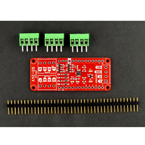
아두이노 MKR/CANZERO 용 12V/24V I/O 디지털/아날로그 입출력 쉴드
(THE GO-24V MKR SHIELD)
개요
- 본 제품은 아두이노 MKR 보드나 CANZERO 보드 용 12V/24V 디지털/아날로그 입출력 쉴드입니다.
- 대부분의 마이크로컨트롤러는 3.3V/5V 로직과 동작합니다.
- 하지만 오토메이션 프로젝트나 산업용 제품중에는 12V/24V와 동작하는 제품들이 흔하고 이런 제품과 마이크로컨트롤러와 연결하여야 되는 경우가 있습니다.
- 이 제품은 이런 경우 사용이 가능합니다.
- 24V 입력이 가능한 GPIO를 가지고 있습니다.
- 4개의 디지털 입력, 4개의 디지털 출력, 2개의 아날로그 입력을 가지고 있습니다.
특징
-
It features:
- 4 digital inputs (0-24V).
- 4 digital open-drain outputs (0-24V), sinking up to 2A.
- 2 analog inputs (0-24V).
The shield also breaks out the GND and VIN pins of the MKR board.
-
The following table provides details of the shield input/output capabilities:
Shield connector Arduino MKR Pin Characteristics Input 1 D0 0-24V Input 2 D1 0-24V Input 3 D2 0-24V Input 4 D3 0-24V Sink 1 (Output) D4 0-24V (max 60V, 3.1A) Sink 2 (Output) D5 0-24V (max 60V, 3.1A) Sink 3 (Output) D6 0-24V (max 60V, 3.1A) Sink 4 (Output) D7 0-24V (max 60V, 3.1A) Analog in 1 A0 0-24V mapped to 0-3.2V Analog in 2 A1 0-24V mapped to 0-3.2V GND GND - VIN VIN - Note that this shield does not feature isolated inputs/outputs (e.g. using optocouplers) or galvanic isolation.
Digital inputs
The digital inputs have the same shifting characteristic as the GPIO of the MCUs they are connected to. For a SAMD21 board like the Arduino MKR Zero or the Omzlo CANZERO, this means that any input below 1V will be considered LOW (0), and any input above 1.8V will be considered as HIGH (1).
Digital outputs
The digital outputs are sinking outputs, which means that they are used to switch loads on the low side, as shown in the picture below.

The sinking outputs are controlled by MOSFETs, which have a comfortable maximum 3.1A current rating. In practice, it's best to keep safely away from those limits. We tested currents up to 1.5A without any issue, for low-side switching power LEDs. Lower currents should also be considered when switching these MOSFETs very rapidly (e.g. through fast PWM). In doubt, please consult the safe operating area of the MOSFET in the datasheet.
Analog inputs
Analog inputs are managed by feeding input voltage in a voltage divider and a buffering op-amp, resulting in a scaled voltage range where 24V corresponds to 3.2V on the analog input of the Arduino-compatible board (and 24.75V corresponds to 3.3V). In terms of accuracy, the voltage divider uses 1% resistors, but the greatest source of inaccuracy can come from the ADC of the MCU itself. It is possible to apply calibration to each board to substantially increase accuracy.
문서
- For more information including schematics and Arduino code, please see our online documentation.


