


 수량을 선택해주세요.


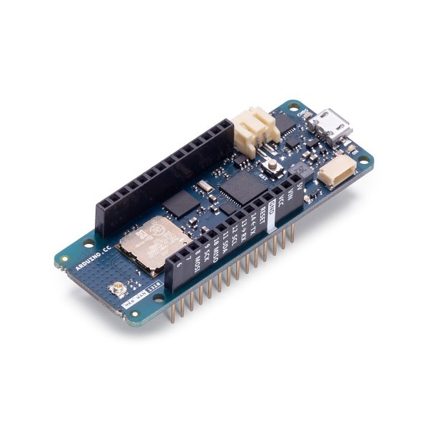
정품 아두이노 MKR WAN 1310 -LoRa
(ARDUINO MKR WAN 1310 W/O ANTENNA)
개요
- 본 제품은 아두이노 MKR WAN 1310 정품입니다.
- 원거리 통신이 가능한 LoRa 무선 프로토콜을 지원하는 아두이노 보드로 Atmel SAMD21 MCU와 Murata CMWX1ZZABZ LoRa 모듈을 탑재하고 있습니다.
- 보드상에 2MB 플래쉬가 탑재되어 있어 데이터 로깅이나 OTA(Over The Air)기능 지원이 가능합니다.
특징
-
Microcontroller SAMD21 Cortex-M0+ 32bit low power ARM MCU (datasheet) Radio module CMWX1ZZABZ (datasheet) Board Power Supply (USB/VIN) 5V Secure Element
ATECC508 (datasheet)
Supported Batteries(*) rechargeable Li-Ion, or Li-Po
Circuit Operating Voltage 3.3V Digital I/O Pins 8 PWM Pins 12 (0, 1, 2, 3, 4, 5, 6, 7, 8, 10, A3 - or 18 -, A4 -or 19) UART 1 SPI 1 I2C 1 Analog Input Pins 7 (ADC 8/10/12 bit)
Analog Output Pins 1 (DAC 10 bit) External Interrupts 8 (0, 1, 4, 5, 6, 7, 8, A1 -or 16-, A2 - or 17) DC Current per I/O Pin 7 mA CPU Flash Memory 256 KB (internal)
QSPI Flash Memory 2MByte (external SRAM 32 KB EEPROM no Clock Speed 32.768 kHz (RTC), 48 MHz LED_BUILTIN 6 Full-Speed USB Device and embedded Host Antenna gain 2dB (bundled antenna at the Arduino Store) Carrier frequency 433/868/915 MHz Working region EU/US (confirmed) for other countries, please confirm the viability of using the radio spectrum. Length 67.64 mm Width 25 mm Weight 32 gr.
문서
-
OSH: Schematics
The MKR WAN 1310 is open-source hardware! You can build your own board using the following files:
EAGLE FILES IN .ZIPSCHEMATICS IN .PDFFRITZING IN .FZPZ
Pinout
The pinout in PNG format will be availabe next week!
Antenna
When purchased at the Arduino Store, the MKR WAN 1310 comes bundled with an antenna that can be attached to the board using the existing micro UFL connector. It is possible to use other antennas using the appropriate pigtail.
When purchasing a different antenna than the one provided (or when making your own), please check that it is tuned for the frequency band in use in the LoRa® / LoRaWAN™ range (433/868/915 MHz). Also avoid placing your antenna in parallel to a ground plane like a large metallic surface.
Batteries, Pins and board LEDs
- Battery capacity: rechargeable Li-Ion, or Li-Po. Please make sure the battery connector suits your battery.
- Battery connector: The connector is of type JST S2B-PH-SM4-TB(LF)(SN).
- Mating connector is JST PHR-2
- Vin: This pin can be used to power the board with a regulated 5V source. If the power is fed through this pin, the USB power source is disconnected. This is the only way you can supply 5v (range is 5V to maximum 6V) to the board not using USB. This pin is an INPUT.
- 5V: This pin outputs 5V from the board when powered from the USB connector or from the VIN pin of the board. It is unregulated and the voltage is taken directly from the inputs.
- VCC: This pin outputs 3.3V through the on-board voltage regulator. This voltage is 3.3V if USB or VIN is used and equal to the series of the two batteries when they are used
- LED ON: This LED is connected to the 5V input from either USB or VIN. It is not connected to the battery power, thus minimizing the impact on battery usage. It is therefore normal to have the board properly running on battery power without the LED ON being lit.
- Onboard LED: On MKR WAN 1310 the onboard LED is connected to D6.


