


 수량을 선택해주세요.


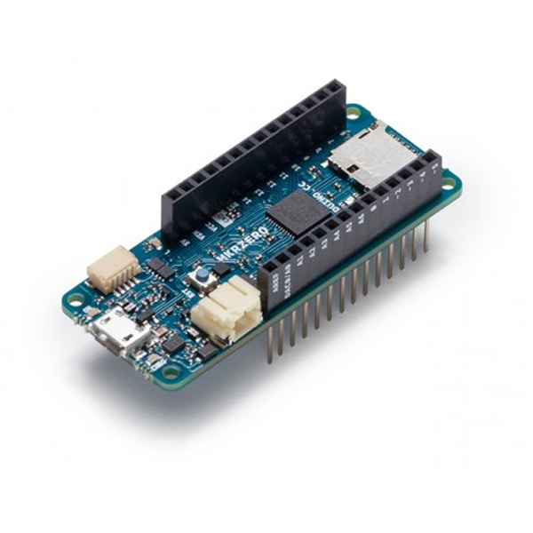
정품 아두이노 MKR 제로 -I2S, SD
(ARDUINO MKR ZERO (I2S BUS & SD FOR SOUND,
MUSIC & DIGITAL AUDIO DATA))
개요
- 본 제품은 아두이노 MKR 제로 보드입니다.
- 오디오 어플리케이션에 사용가능한 I2S 인터페이스와 전용 SPI를 가진 SD 커넥터를 지원합니다.
- micro USB 커넥터와 리포배터리를 연결할 수 있는 커넥터를 지원합니다.
- 32비트 ARM Cortex M0+ SAMD21 MCU를 장착하고 있으며, 아래의 두개의 라이브러리를 지원합니다.
- Arduino Sound library – a simple way to play and analyze audio data using Arduino on SAM D21-based boards.
- I2S library – to use the I2S protocol on SAMD21-based boards. For those who don't know, I2S (Inter-IC Sound) is an electrical serial bus interface standard for connecting digital audio devices.
- 알림: I/O 레벨은 3.3V입니다. 5V사용시 보드 손상됩니다.
특징
-
Microcontroller SAMD21 Cortex-M0+ 32bit low power ARM MCU Board Power Supply (USB/VIN) 5V Supported Battery(*) Li-Po single cell, 3.7V, 700mAh minimum DC Current for 3.3V Pin 600mA DC Current for 5V Pin 600mA Circuit Operating Voltage 3.3V Digital I/O Pins 22 PWM Pins 12 (0, 1, 2, 3, 4, 5, 6, 7, 8, 10, A3 - or 18 -, A4 -or 19) UART 1 SPI 1 I2C 1 Analog Input Pins 7 (ADC 8/10/12 bit) Analog Output Pins 1 (DAC 10 bit) External Interrupts 9 (0, 1, 4, 5, 6, 7, 8, A1 -or 16-, A2 - or 17) DC Current per I/O Pin 7 mA Flash Memory 256 KB Flash Memory for Bootloader 8 KB SRAM 32 KB EEPROM no Clock Speed 32.768 kHz (RTC), 48 MHz LED_BUILTIN 32 Full-Speed USB Device and embedded Host
문서
-
OSH: Schematics
The MKR ZERO is open-source hardware! You can build your own board using the following files:
EAGLE FILES IN .ZIPSCHEMATICS IN .PDFLi-Po batteries, Pins, SD and board LEDs
On-board SD
The on- board SD connector allows you to play with files without adding any extra hardware to the board. Furthermore SD card is driven by a dedicated SPI interface (SPI1) and so any of the pins of the header is busy during SD usage. The SD library automatically recognizes the MKR ZERO and so any modification to the sketch is needed to use it aprat from choosing the right SS pin (SDCARD_SS_PIN).
Battery capacity
Li-Po batteries are charged up to 4,2V with a current that is usually half of the nominal capacity (C/2). For Arduino MKR ZERO we use a specialized chip that has a preset charging current of 350mAh. This means that the MINIMUM capacity of the Li-Po battery should be 700 mAh. Smaller cells will be damaged by this current and may overheat, develop internal gasses and explode, setting on fire the surroundings. We strongly recommend that you select a Li-Po battery of at least 700mAh capacity. A bigger cell will take more time to charge, but won't be harmed or overheated. The chip is programmed with 4 hours of charging time, then it goes into automatic sleep mode. This will limit the amount of charge to max 1400 mAh per charging round.
Battery connector
If you want to connect a battery to your MKRZero be sure to search one with female 2 pin JST PHR2 Type connector. Polarity : looking at the board connector pins, polarity is Left = Positive, Right = GND Connector datasheet On the MKRZero, connector is a Male 2pin JST PH Type
Additional I2C Port
The MKR Zero has an additional connector meant as an extension of the I2C bus. It's a small form factor 5-pin connector with 1.0mm pitch. The mechanical details of the connector can be found in the connector datasheet. The I2C port in addition to the SDA and SCL signals includes the GND and +5V power rails and a digital pin that might be useful when designing an expansion. The pinout is shown in the following image:

The connector we suggest for this additional I2C Port is the SHR-05V-S-B, also in the picture.
Vin
This pin can be used to power the board with a regulated 5V source. If the power is fed through this pin, the USB power source is disconnected. This is the only way you can supply 5v (range is 5V to maximum 6V) to the board not using USB. This pin is an INPUT.
5V
This pin outputs 5V from the the board when powered from the USB connector or from the VIN pin of the board. It is unregulated and the voltage is taken directly from the inputs. As an OUTPUT, it should not be used as an input pin to power the board.
VCC
This pin outputs 3.3V through the on-board voltage regulator. This voltage is the same regardless the power source used (USB, Vin and Battery).
LED ON
This LED is connected to the 5V input from either USB or VIN. It is not connected to the battery power. This means that it lits up when power is from USB or VIN, but stays off when the board is running on battery power. This maximizes the usage of the energy stored in the battery. It is therefore normal to have the board properly running on battery power without the LED ON being lit.
CHARGE LED
The CHARGE LED on the board is driven by the charger chip that monitors the current drawn by the Li-Po battery while charging. Usually it will lit up when the board gets 5V from VIN or USB and the chip starts charging the Li-Po battery connected to the JST connector. There are several occasions where this LED will start to blink at a frequency of about 2Hz. This flashing is caused by the following conditions maintained for a long time (from 20 to 70 minutes): - No battery is connected to JST connector. - Overdischarged/damaged battery is connected. It can't be recharged. - A fully charged battery is put through another unnecessary charging cycle. This is done disconnecting and reconnecting either VIN or the battery itself while VIN is connected.
Onboard LED
On MKR ZERO the onboard LED is connected to a dedicated pin (32) and not to 13 as on other boards. It is so suggested to use the LED_BUILTIN define .
(*) Note : DO NOT CONNECT to the male JST connector present on the board anything else than a Li-Po battery whose characteristics are compliant with those indicated above. Please DO NOT POWER VIN with more than 5V.


