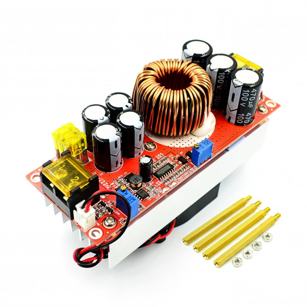
When the power supply is unloaded, use a flat-blade screwdriver to adjust the output terminal "V-ADJ" potentiometer (marked in the figure below) to increase clockwise and counterclockwise to adjust). Because the output capacitor capacity is large, the output voltage is When the high voltage is adjusted to a low voltage, the reaction will be slower. The adjustment of the instrument is smaller.
Adjust the "CC A-ADJ" potentiometer counterclockwise for about 30 turns, set the output current to the minimum, connect the load such as the LED battery, and adjust the "CC A-ADJ" potentiometer clockwise to the current you need. For battery charging, after the battery is discharged, it is connected to the output, and adjust the CC A-ADJ to the current you need. When charging, be sure to use the discharged battery to adjust the battery. The more the charge, the smaller the charge current. The default output ESC is shipped to 10A. If we need to adjust the current value of the instructions or message. Do not use the short-circuit output to adjust the current, the circuit structure of the boost module can not be adjusted by short circuit.
Enter low battery protection adjustment:
Low battery protection is mainly to prevent over-discharge of the battery when the input power is the battery. The battery voltage is too low to damage the power module and the battery. When the input is a switching power supply, the low voltage protection should also be set.
Method 1: For example, set 12V battery low battery protection. Connect a voltage of 11V to the input terminal of the power module. Use a flat-blade screwdriver to adjust RV1 (clockwise protection voltage value is increased, counterclockwise protection voltage is turned down) until the UVLO lamp is on. At this time, the low battery protection voltage is 11V. When the voltage drops to 11V, the power module does not rise (the input voltage is equal to the output voltage). Only after the input voltage is higher than 11V, the power supply starts to resume boosting.
Method 2: Input the battery or switch power supply. If the UVLO lamp on the board is off, adjust the RV1 potentiometer clockwise, brighten the UVLO lamp, and then turn it clockwise two turns. If the UVLO lamp is on, turn the RV1 potentiometer counterclockwise, turn off the UVLO lamp, and then turn it two turns. (Adapt to 10V-45V voltage)
Precautions:
(1) The output positive and negative poles cannot be reversed and cannot be short-circuited.
(2) If used for electric vehicle boost drive power supply, the input voltage must be 24V or more. The electric vehicle power is less than 500W. Because the electric motor is an inductive load, the current will be large at the moment of starting and uphill. There must be sufficient power headroom.
(3) When using batteries, switching power supplies, solar panels, generators, etc. as input sources, battery protection must be lowered, otherwise the battery and power supply may be damaged.
(4) Pay attention to ventilation and heat dissipation when working for a long time, high current, high power and full load, in order to extend the service life of the power supply.
(5) The module can only boost the voltage and cannot supply voltage to the electrical equipment below the input voltage. For example, charge the 12V battery with a 24V battery or charge the capacitor. Powering the lED below the input voltage
(6) Do not work at full load for a long time. Please keep 20% margin when working continuously, pay attention to ventilation and heat dissipation.


 수량을 선택해주세요.