


 수량을 선택해주세요.


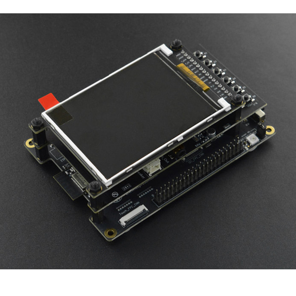
ESP32-S2-Kaluga-1 개발 보드 -3.2인치 터치 LCD
(ESP32-S2-Kaluga-1 Development Board Kit)
개요
- 본 제품은 Espressif 사의 ESP32-S2-Kaluga-1 개발 보드입니다.
- ESP32-S2의 HMI(human-computer interaction) 기능을 검증하고 테스트하여 볼 수 있는 툴을 제공하는 제품입니다.
- 3.2인치 터치 LCD, 카메라 이미지 인식 기능, 오디오 플레이 등의 기능을 지원합니다.
특징
-

Touch Panel Control
- 14 touch sensors, three of which support distance detection(proximity mode)
- Support acrylic panels up to 5mm
- Wet hand operation
- Mis-touch prevention; water rejection: ESP32-S2 can be configured to disable all touchpads automatically if multiple pads are simultaneously covered with water and to re-enable touchpads if the water is removed.
Audio Playback
- Connect speakers to play audio
- Use together with the Touch panel to control audio playback and adjust volume
LCD Display
- LCD interface(8-bit parallel RGB, 8080, and 6800 interface)
- Support display with ST7789 and ILI9341 driver
- Support camera data real-time display on LCD screen
Camera Image Acquisition
- Support OV2640 and OV3660 camera modules
- 8/16-bits DVP image sensor interface
- Clock frequency up to 40MHz
- Optimized DMA transmission bandwidth for easier transmission of high-resolution images
Description of Components


Key Component
Description
ESP32-S2-WROVER Module
Module integrating the ESP32-S2 chip that provides Wi-Fi connectivity, data processing power, and flexible data storage.
4.3" LCD FPC Connector
(Reserved) Connect to a 4.3" LCD extension board using the FPC cable.
ESP Prog Connector
(Reserved) Connection for Espressif's download device (ESP-Prog) to flash ESP32-S2 system.
JTAG Switch
Switch to ON to enable connection between ESP32-S2 and FT2232; JTAG debugging will then be possible using USB-UART/JTAG Port. See also JTAG.
Breakout Header 2
Some GPIO pins of the ESP32-S2-WROVER module are broken out to this header, see labels on the board.
USB-to-UART/JTAG Bridge
FT2232 adapter board allowing for communication over USB port using UART/JTAG protocols.
Camera Header
Mount a camera extension board here (e.g., ESP-LyraP-CAM).
Extension Header
Mount the extension boards having such connectors here.
Reset Button
Press this button to restart the system
Boot Button
Holding down Boot and then pressing Reset initiates Firmware Download mode for downloading firmware through the serial port.
USB-UART/JTAG Port
Communication interface (UART or JTAG) between a PC and the ESP32-S2 module.
USB Power Port
Power supply for the board.
Battery Port
Connect an external battery to the 2-pin battery connector.
Power On LED
Turns on when the USB or an external power supply is connected to the board.
Power Switch
Switch to ON to power the system.
RGB Jumper
To have access to the RGB LED, place a jumper onto the pins.
RGB LED
Programmable RGB LED and controlled by GPIO45. Before using it, you need to put RGB Jumper ON.
Power Regulator
Regulator converts 5 V to 3.3 V.
I2C FPC Connector
(Reserved) Connect to other I2C extension boards using the FPC cable.
Breakout Header 1
Some GPIO pins of the ESP32-S2-WROVER module are broken out to this header, see labels on the board.
Touch FPC Connector
Connect the ESP-LyraP-TouchA extension board using the FPC cable.
Touch Switch
In OFF position, GPIO1 to GPIO14 are used for connection to touch sensors; switch to ON if you want to use them for other purposes.
3.2" LCD FPC connector
Connect a 3.2" LCD extension board (e.g., ESP-LyraP-LCD32) using the FPC cable.
-
SHIPPING LIST
- ESP 32-S2-Kaluga-1 ×1
- ESP-LyraT-8311A ×1
- ESP-LyraP-CAM ×1
- ESP-LyraP-TouchA ×1
- ESP-LyraP-LCD32 ×1
- 20-Pin FPC Cable(to connect ESP32-S2-Kaluga-1 to ESP-LyraP-TouchA) ×1
- Mounting Bolts ×8
- Screws ×4
- Nuts ×4


