


 수량을 선택해주세요.


24 비트 ADC 모듈 - ADS122U04
(ADC 10 CLICK)
개요
- 본 제품은 24 비트 ADC 모듈 - ADS122U04입니다.
- 24 비트 ADS122U04 ADC 칩을 기반으로 디자인된 제품입니다.
- UART 인터페이스를 가지고 있습니다.
- 두개의 차동 입력이나 네개의 싱글 엔드 입력 및 프로그래밍 가능한 게인 앰프, excitation current 소스, 전압 리퍼런스, 오실레이터, 온도 센서를 지원합니다.
- 초당 2000 샘플의 샘플링을 지원합니다.
- RTD 센서, 써모커플, 써미스터, resistive bridge 센서의 신호를 측정하는데 적합한 제품입니다.
특징
-
Type ADC Applications Can be used for measuring small sensor signals, such as resistance temperature detectors (RTDs), thermocouples, thermistors, and resistive bridge sensors. On-board modules ADS122U04 - 24-bit precision ΔΣ analog-to-digital converter with UART compatible interface from Texas Instruments MCP1501 - high-precision voltage reference from Microchip LT6656 - high-precision voltage reference from Analog Devices Key Features Low power consumption, programmable gain and data rates, two differential or four single-ended inputs, internal and external voltage references, internal temperature sensor, and more Interface UART Compatibility mikroBUS Click board size M (42.9 x 25.4 mm) Input Voltage 3.3V or 5V -
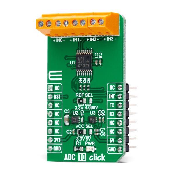
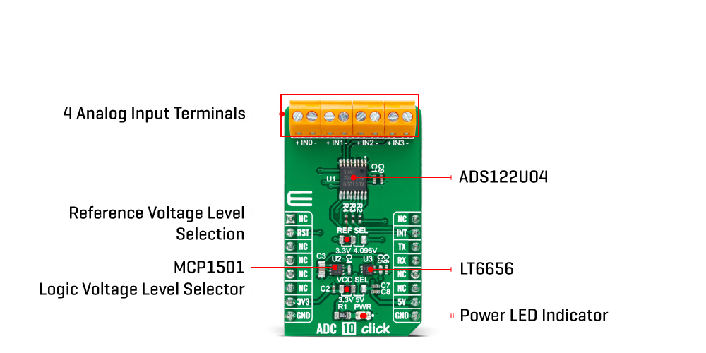
ADC 10 Click is based on the ADS122U04, a 24-bit precision ΔΣ analog-to-digital converter with UART compatible interface from Texas Instruments. In addition to the ΔΣ ADC and single-cycle settling digital filter, the ADS122U04 offers a low-noise, high input impedance, programmable gain amplifier up to 128, an internal 2.048V voltage reference, and a clock oscillator. It also integrates a highly linear and accurate temperature sensor, and two matched programmable current sources for sensor excitation. The ADS122U04 is fully configured through five registers through the UART interface and can perform conversions at data rates up to 2000 samples-per-second with single-cycle settling.
The A/D converter measures a differential signal brought to its input terminals, which represents the difference in voltage between the + and – nodes of the input terminal. The ADS122U04 has two available conversion modes: Single-Shot conversion and Continuous conversion Mode. In Single-Shot conversion Mode, the ADC performs one conversion of the input signal upon request, stores the value in an internal data buffer, and then enters a low-power state to save power. While in Continuous conversion Mode, the ADC automatically begins the conversion as soon as the previous conversion is completed.
ADC 10 Click communicates with MCU using the UART interface at 115200bps with commonly used RX and TX pins for the data transfer. The interrupt pin routed on the INT pin of the mikroBUS™ socket is utilized by ADS122U04 to indicates when a new conversion result is ready for retrieval or can be additionally configured as a GPIO pin. Alongside this feature, this Click board™ also has a Reset function routed on the RST pin of the mikroBUS™ socket that will put the ADS122U04 into the reset state by driving the RST pin HIGH. When a Reset occurs, the configuration registers reset to the default values, and the device enters a low-power state.
Besides its internal 2.048V reference, the ADS122U04 can use additional reference voltage values for applications that require a different reference voltage or a ratiometric measurement approach. The reference voltage level can be selected by positioning the SMD jumper labeled as REF SEL to an appropriate position choosing between 3.3V provided by the MCP1501 or 4.096V provided by LT6656. Those voltages may be used as the reference input that results in accuracy and stability.
This Click board™ is designed to operate with both 3.3V and 5V logic voltage levels selected via the VCC SEL jumper. It allows for both 3.3V and 5V capable MCUs to use the UART communication lines properly. However, the Click board™ comes equipped with a library that contains functions and an example code that can be used, as a reference, for further development


