


 수량을 선택해주세요.


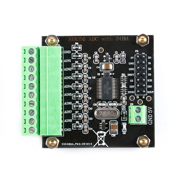
ADS1256 24비트 ADC 모듈 -SPI
(ADS1256 24-bit ADC Module)
개요
- 본 제품은 멀티플렉서를 내장한 TI 사의 ADS1256 24비트 ADC 칩을 탑재한 모듈입니다.
- 8개의 채널을 ADC할 수 있으며, SPI인터페이스를 통해서 마이크로컨트롤러와 인터페이스 할 수 있습니다.
- SPI인터페이스를 가지고 있습니다.
특징
-
Module power supply: DC5V
Module current: 15mA (MAX)
Module communication protocol: SPI serial
Module control signal level: 3.3V
Module input voltage range: 0-5V
Input impedance: 1M ohm
ADC resolution digits: 24 bits; effective bits 18 bits
Sampling rate: 30KSPS; single channel does not switch up to 30K, the sampling rate decreases when using multiple channels
Number of input channels: 8-channel single-ended, 4-channel pseudo differential; time-sampling
Module input interface: 3.81-10PIN terminal
Reference voltage: external 2.5V; external input reference for soldered SOT-23 package
PGA mode: 7; 1x, 2x, 4x, 8x, 16x, 32x, 64x
Output mode: 8-channel data serial
Module features: multiple; low noise analog front end, optional digital filtering, up to 23 noise-free resolutions
Module application: multiple; industrial process control, motion signal acquisition, industrial signal acquisition
Module interface type: 3.81-10PIN socket, XH2.54 double-row pin data interface
Measuring range:
Gin rangea
1 ±5V
2 ±2.5V
4 ±1.25V
8 ±0.625V
16 ± 0.3125v
32 ± 0.1563V
64 ± 0.0781V
Chip characteristics:
*24 Bits, Lossless Code - All Data Rates and PGA Settings
*Up to 23 bits noise-free resolution
*Non-linearity (±0.0010%)
*Data Output Rate 30 kSPS
*Fast Channel Cycle - 18.6 Bit Noise Free (21.3 Significant Bit) at 1.45 kHz
*Single Conversion and Single Period Stability
*Flexible Input Multiplexer and Sensor Detection-
Four differential inputs (only ADS1256)
Eight single-ended inputs (only ADS1256)
*Chopper stabilized input buffer
*Low Noise PGA:27nV Input Reference Noise
*Self and System Calibration of All PGA Settings
*5V Voltage-withstanding SPI Compatible Serial Interface
*Analog power supply: 5V digital power supply: 1.8V to 3.6V
*Power consumption-
Low to 38MW in normal mode
-0.4mW Standby Mode
Note: The chip features are only for user selection reference. Non-modules have this feature

-
Precautions for using the module
(1) The module is a low-power module, and the power supply does not exceed 6V.
(2) Since the module is a high-precision device, in order to avoid unnecessary interference, it is recommended to use a linear power supply.
(3) The output signal line is recommended to be as short as possible, too long to easily introduce noise signals. Poor contact or poor quality wires may cause signal attenuation or excessive noise.
(4) The delivered code is only used for the supporting main control board; the microcontroller tutorial is not provided, and functions other than product details display need to be developed by yourself.
(5) If you need to simply test the function of the module, it is recommended to use it with the control board of our store. After the correct wiring, power the control board to achieve signal acquisition and display.
Frequently asked questions
Q: For example, if you give a voltage: 4.1234V, let it collect all the time. What is the result? Will the value jump?
A: The data must be beating. This is not determined by a single condition. The theoretical value can reach 0.1mv. Actual measurement: a better power supply can be stable at 1mv.
Q: Can ADS1256 directly transfer data to PLC?
A: Generally speaking, the PLC level is not compatible with the ADS1256 module. Our module is a 3.3V communication level. Generally, a single chip can be used for communication.
Q: Both AD7190 and ADS1256 are 24-bit ADCs, which are the same in many places. What is the difference in use? .
A: Generally speaking, AD7190 is more used in load cells or pressure sensors. The true differential between channels; ADS1256 is pseudo differential. The acquisition speed of ADS1256 is faster than that of AD7190.
Q: If I use ADS1256 and the matching main control board and use the USB port to supply power, I cannot collect a voltage of 5V?
A: Since the voltage of the universal USB port is lower than 5V, the power supply voltage of the ADS1256 chip will be less than 5V, so the voltage of 5V cannot be collected. It is recommended to use the DC interface, power supply above 5V, but not more than 5.5V , So that you can collect a 5V voltage.
Q: The small voltage signal collected by ADS1256 is inaccurate, and there is no value after using internal PGA; what is the situation?
A: The ADS1256 default is to open the internal BUFFER. BUFFER has a certain offset voltage, which will lead to inaccurate signal acquisition near 0 voltage. The program can be closed. The second is that the premise of using the internal PGA is to ensure that the amplified voltage If it is less than 5V, otherwise the magnification is too large and the value will not be collected.
Q: After the module is driven normally, the pins that are not connected to voltage show that there is voltage, is it normal? .
A: The module collects 8 channels at the same time by default. When no voltage is connected, the floating voltage on the pin is also collected. The pin can be directly grounded, which is 0 voltage.


