


 수량을 선택해주세요.


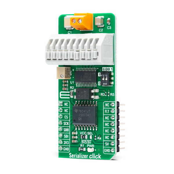
24V - 5V 디지털 입력 변환 SPI 모듈 -MAX31910
(SERIALIZER CLICK)
개요
- 본 제품은 24V - 5V 디지털 입력 변환 SPI 모듈 -MAX31910입니다.
- 8채널 디지털 입력 시리얼 라이저 MAX31910 칩을 장착하고 있습니다.
- 센서의 24V 디지털 출력을 MCU에서 사용이 가능한 5V CMOS 호환 신호로 변경하여 줍니다.
- 주로 PLC의 입력 인터페이스를 변환하고자 할때 사용이 가능한 제품입니다.
- SPI 인터페이스를 가지고 있습니다.
특징
-
HOW DOES IT WORK?
Serializer Click as its foundation uses the MAX31910, an eight-channel digital input translator/serializer for high-channel density digital input modules in industrial and process automation from Maxim Integrated, now part of Analog Devices. It features integrated current limiting, low-pass filtering, and channel serialization. Input current limiting allows a significant reduction in power consumed from the field voltage supply (external typical 24V) compared to traditional discrete resistor-divider implementations. The device uses patent-pending circuit techniques to further reduce power beyond possible input current limiting alone.
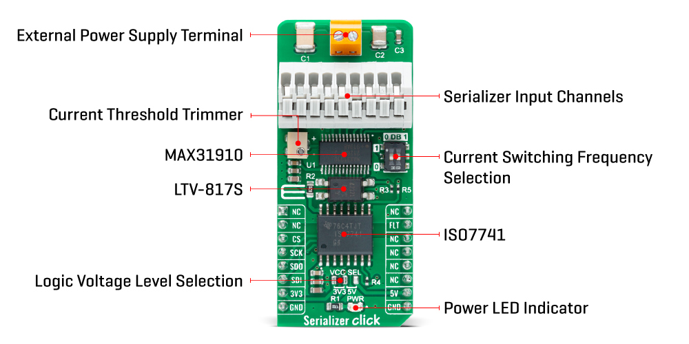
The MAX31910 translates, conditions, and serializes the 24V digital output of sensors and switches to 5V CMOS-compatible signals required by the MCU. It provides the front-end interface circuit of a programmable logic controller (PLC) digital input module. Selectable on-chip low-pass filters allow flexible debouncing and filtering sensor outputs based on the application. The serializer is stackable so that any number of input channels (IN1-IN8) can be serialized and output through only one SPI-compatible port.
The serializer inputs (IN1-IN8) sense the state (ON vs. OFF) of field sensors by monitoring both voltage and a current flowing through the sensor output. The current sinking through these input pins rises linearly with input voltage until the limit set by the current clamp is reached (set by an onboard potentiometer). Any voltage increase beyond this point does not further increase the input current.
Serializer Click communicates with MCU through a standard SPI interface in a configuration with installed digital isolators (ISO7741 and LTV-817S). Also, it uses an interrupt pin, the FLT pin of the mikroBUS™ socket, used as a 'fault' indicator which immediately notifies the host when a fault such as an overtemperature or undervoltage condition occurs. It also has a two-channel switch labeled DB, which determines the current switching frequency. The current switching clock period is automatically selected according to a switch position.
This Click board™ can operate with both 3.3V and 5V logic voltage levels selected via the VCC SEL jumper. This way, it is allowed for both 3.3V and 5V capable MCUs to use the communication lines properly. However, the Click board™ comes equipped with a library containing easy-to-use functions and an example code that can be used, as a reference, for further development.
-
Type Measurements Applications Can be used for various applications such as industrial, process, and building automation, digital input modules for PLCs, and more On-board modules MAX31910 - eight-channel digital input translator/serializer from Maxim Integrated, now part of Analog Devices Key Features Low power consumption, highly integrated, eight channels, robust features and performance for industrial environments, flexible power supply capability, and more Interface SPI Compatibility mikroBUS Click board size L (57.15 x 25.4 mm) Input Voltage 3.3V or 5V,External


