


 수량을 선택해주세요.


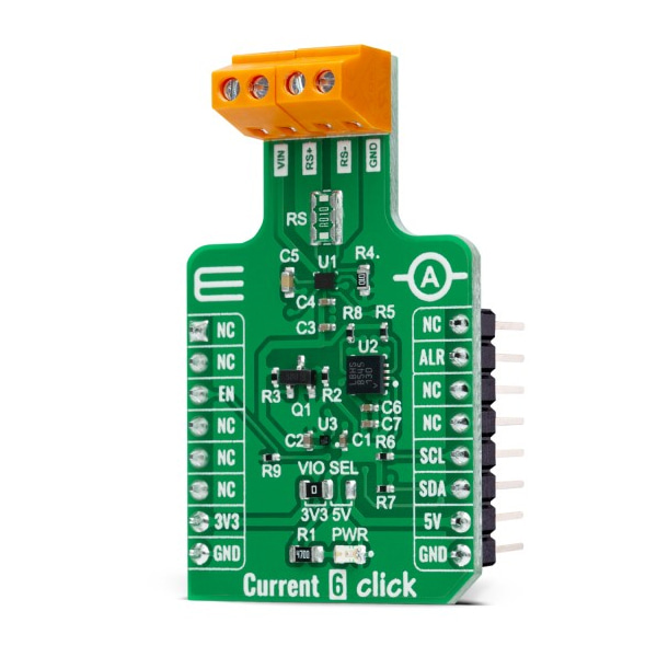
전류 측정 센서 -MAX40080
(CURRENT 6 CLICK)
개요
- 본 제품은 전류 측정 센서 -MAX40080입니다.
- MAX40080 칩을 탑재하고 있으며, I2C 인터페이스를 가지고 있습니다.
- 3.3V 및 5V 시스템과 사용이 가능합니다.
특징
-
HOW DOES IT WORK?
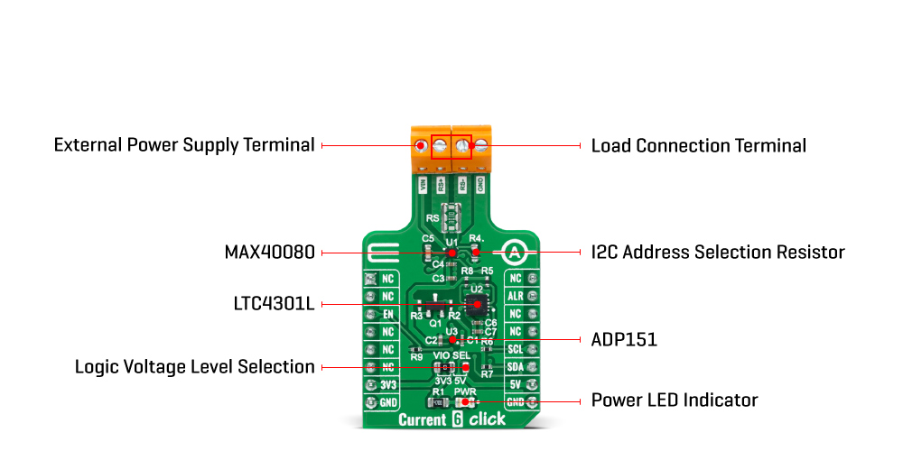
Current 6 Click as its foundation uses the MAX40080, a high-precision, fast sample-rate digital current-sense amplifier from Analog Devices. The MAX40080 measures current and common-mode voltage ranging from -0.1V to 36V and converts the data into digital form through an I2C-compatible two-wire serial interface allowing access to conversion results. Also, setting the input voltage sense using the I2C register, ±50mV or ±10mV, will allow one to select two measuring ranges from 0A to 1A or from 0A to 5A.
This Click board™ communicates with MCU using the standard I2C 2-Wire interface for configuring and checking the device's status. Standard I2C commands allow reading the data and configuring other operating characteristics. While reading the current/voltage registers, any measured current and voltage changes are ignored until the read is completed. The current/voltage register is updated for the new measurement upon completion of the read operation.
The MAX40080 has a unique I2C slave address selection method based on a single R4 resistor. By selecting the resistors of precisely defined resistances from Table 1, it is possible to choose 32 different slave addresses corresponding to 32 different resistor values in the attached datasheet. The default value of the R4 resistor is 100kΩ which corresponds to slave address of 0x01. In addition, it also features a wake-up current-threshold and auto-shutdown mode when the I2C interface is inactive, both designed to minimize power consumption.
Since the sensor for operation requires a 1.8V logic voltage level to work correctly, a small regulating LDO is used, the ADP151 from Analog Devices, providing a 1.8V out of mikroBUS™ rails. This LDO uses the Enable pin labeled as EN and routed to the CS pin of the mikroBUS™ socket to optimize power consumption, used for its power ON/OFF purposes. That's why the LTC4301L voltage-level translator is also featured. The I2C interface bus lines are routed to the voltage-level translator, allowing this Click board™ to work with both 3.3V and 5V MCUs properly. It also possesses an additional interrupt signal, routed on the INT pin of the mikroBUS™ socket labeled as INT, indicating when a specific interrupt event occurs such as overcurrent/voltage, under voltage, FIFO full/overflow, wake-up current threshold reached, and more.
This Click board™ can operate with both 3.3V and 5V logic voltage levels selected via the VIO SEL jumper. This way, it is allowed for both 3.3V and 5V capable MCUs to use the communication lines properly. However, the Click board™ comes equipped with a library containing easy-to-use functions and an example code that can be used, as a reference, for further development.
-
Type Measurements Applications Can be used for industrial control and automation applications, load and power supplies monitoring, telecom equipment, and many more On-board modules MAX40080 - high-precision, fast sample-rate digital current-sense amplifier from Analog Devices Key Features Wide input common-mode range up to 36V, I2C interface with smart modes, low power consumption, bi-directional current sensing, alert interrupt, and more Interface I2C Compatibility mikroBUS Click board size M (42.9 x 25.4 mm) Input Voltage 3.3V or 5V,External


