


 수량을 선택해주세요.


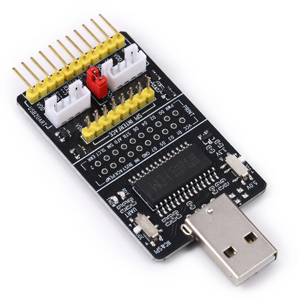
CH341A USB 버스 컨버터 모듈 -SPI/I2C/UART/RS232/RS485
(CH341A USB Bus Conveter Module - SPI/I2C/UART/RS232/RS485/etc)
개요
- 본 제품은 CH341A USB 버스 컨버터 모듈 -SPI/I2C/UART/RS232/RS485입니다.
- CH341A 칩을 기반으로 디자인된 제품으로 USB를 통해 SPI/I2C/UART/RS232/RS485 통신을 할 수 있습니다.
- SPI/I2C/UART/RS232/RS485 인터페이스를 가진 장치와 연결하여 사용이 가능합니다.
특징
- Product Features: CH341A USB control chip inside
- Full-speed USB interface, compatible with USB V2.0, the design of the standard USB-A male;
- Computer USB power supply, the simulation standard serial, used to upgrade serial peripherals, additional serial port, or via USB;
- Supports 3.3V and 5V TTL target system, the serial application is fully compatible with the computer-side under the Windows operating system;
- Support for 5, 6, 7, or 8 data bits, odd parity, even parity, blank, signs, and no parity;
- Support for serial port to send to enable serial receive ready transmission rate control signal and MODEM liaison signal;
- By adding level converter module, RS232, RS485, interface; (supporting modules for sale)
- Provide two parallel port interface modes: EPP mode and MEM mode; USB to parallel port can be used for simple digital I / O control;
- Support for a variety of serial communication modes, UART, I2C, SPI;
- Supports 2-wire and 4-wire synchronous serial interface, I2C supports four kinds of transmission speeds;
- The perfect support for the STC the MCU download and debugging STC official recommended program;
- Support for out output voltage, selectable 3.3V 5V or not output;
- Support the work status indicators;
- Dual interface output;
- Hardware full-duplex serial port, built-in send and receive buffer, and support the communication baud rate 50bps ~ 2Mbps.
- Support WINDOWS 98/ME/2000/XP/server 2003/VISTA/server 2008/WIN 7/64/32-bit.
문서
-
Recommended Software:
Applications:
Simulation of the standard serial port for the upgrade serial peripherals, additional serial port or via USB.
Need to use I2C, SPI, UART, TTL serial and other occasions;
Electronics Engineers debugging download;
Variety of hardware systems, software system debugging;
Serial Brush;How to use:
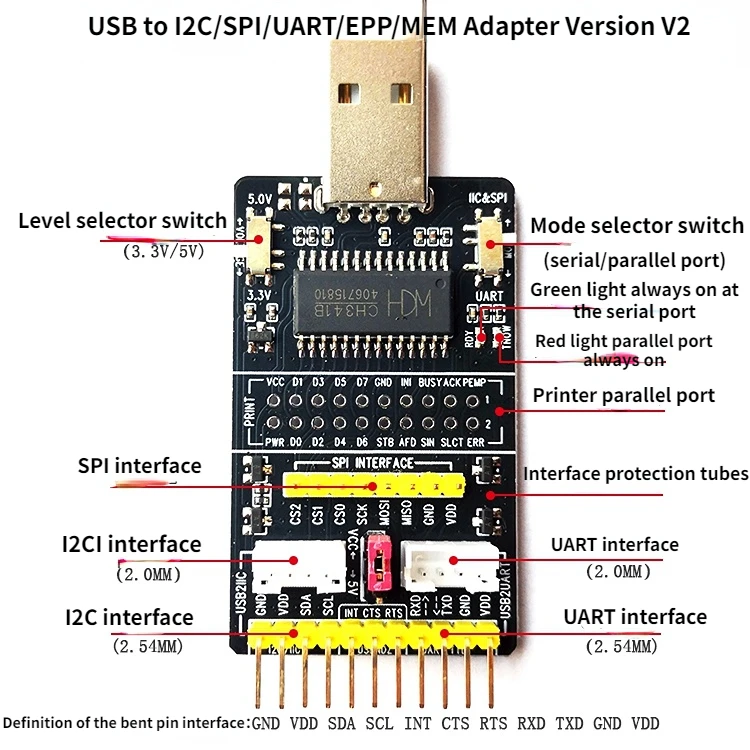
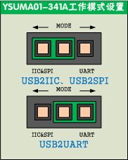
1. Mode Select:
2. Level Select:
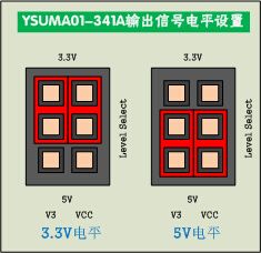
3. Voltage Select: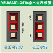
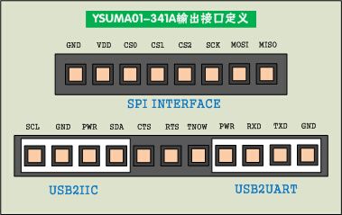
4. Output Interface:
- Some pain to find the sw and the driver, so i copied it on my Google Drive space
What occurred is the USB2I2C program so: need to download also MSSTDFMT.DLL to create the application (in VB !!!), register it with regsvr32 MSSTDFMT.DLL and register also tabctl32.ocx using regsvr32 tabctl32.ocx
Now, I can exec the program to talk to I2C device.Cool! it's work now. But how it works?
Find the spec of the bus converter chip (CH341A) but no real useful information. The real way to understand how to use this adapter is to understand how I2C works:
1.send Address info with read or write bit
2.send offset byte: from which address start the read or the write
3. define how many byte read or write.
Look at the following pic finded on the doc package...everything now is clear...or I hope so!

I2C read operation using the USB adapter 
I2C write operation using the USB adapter
Try now to read some and write some info from the simplest I2C device on my collection, a 24c02 eeprom device (buyed from dx.com). This one:
Using the dedicated panel of the control sw works smooth. I can read and write the data on my flash 2 k memory. Now start to read the data using the other panel (most general one) to be sure that I have understud how it works.
Atmel 24c02 connected to USB Converter
Set the length field with 2 byte (all is hex notation), the data with the address of the device. Here start the problem. You need to use always the write addressing (LSB to 0) and use the "data to read" field to choose if you are writing (set to 0) or reading (set to the correct length)
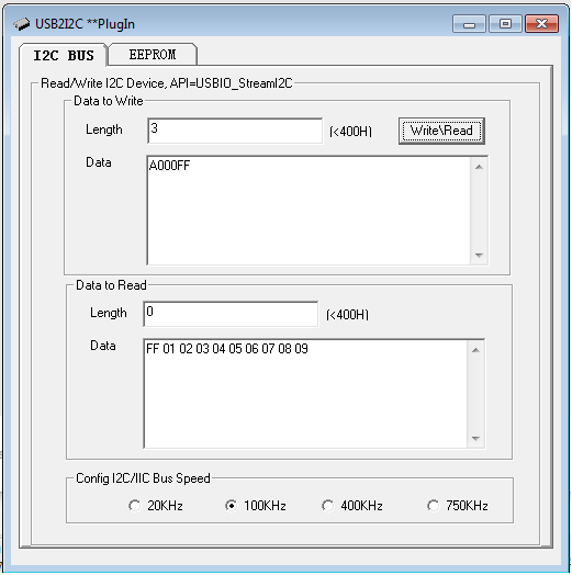
For this example,i want to write "FF" at the first cell of the memory.
1. Put "3" in the "length" field in "write panel"
2. Put "A000FF" in the "data" field (the address of the chip is A0 (10100000), 00 is the offset address and FF is the data to write)
3. Put "0" in the "length" field in data to read field
4. Push "read/write" button...remember..the Data field in "data to read" dont change. You need to read it !
To read some data:
1. Set "2" in the "length" field in "write panel"
2. Set "A000" in the "data" field in "write panel" ( Address in write mode is "A0", offset is "00")
3. Put "A" in the length field of the "data to read" panel
 Now some more funny test.
Connect a Clock I2C module based on Atmel DS3231. I need to persist the current data to the Jumping Sumo, so... use this module bought on dx.com than also got a 24 k eeprom based on a 24c32 device and a battery. This is the pic of the module:
Try to read hours, minute and second from DS3231 chip:
DS3231 High Precision Real-Time Clock Module
1. Set "2" in the "length" field in "data to write" panel2. Set "D000" in the "data" field on "data to wite" panel (D0 is the write address of the clock device)3. Set "3" in the "length" field in "data to read" panel4. Got some like "38 15 10" --> looking at the specs of the clock chip, the first byte are second, the second byte is the hours and the last is the day...as usual in hex format.
Try to read the temperature:
1. Set "2" in the "length" field in "data to write" panel2. Set "D011" in the "data" field on "data to wite" panel (D0 is the write address of the clock device, 11 is the offset's registry)3. Set "2" in the "length" field in "data to read" panel4. Got some like "1A 80" looking again at the specs of the clock chip, the first byte are the MSB of the temp and the second...well, got the first 2 bit, convert to dec and divide by 4!
So:1A == 26d, 80==10000000,convert to dec the first 2 bit(10 == 2d) and divide for 4 =0,5...at the end the temperature is 26+0,5 °C
Here the full memory map of the ds3231 device

DS3231 memory map


연관제품
- 연관제품 1


