


 수량을 선택해주세요.


디지털 포텐셔미터 -AD5142A
(DIGI POT 12 CLICK)

개요
- 본 제품은 디지털 포텐셔미터 -AD5142A입니다.
- 듀얼 채널 256 포지션 디지털 포텐셔미터 AD5142A칩을 장착하고 있습니다.
- I2C 로 제어되는 두개의 포텐셔미터를 제공합니다.
특징
-
HOW DOES IT WORK?
DIGI POT 12 Click is based on the AD5142A, a dual-channel, 256-position nonvolatile digital potentiometer from Analog Devices. The resistor wiper position is determined by the RDAC register contents, that act as a scratchpad register, allowing unlimited changes of resistance settings. The scratchpad register can be programmed with any position setting using the standard I2C interface by loading the 16-bit data word. The nominal resistance of the RDAC between terminals A and terminals B (RAB) is 10KΩ with 8-bit RDAC latch data decoded to select one of the 256 possible wiper settings. When a desired position is found, this value can be stored in the onboard EEPROM memory; thus, the wiper position is always restored for subsequent power-ups. The EEPROM data can be read back, written independently, and protected by software.
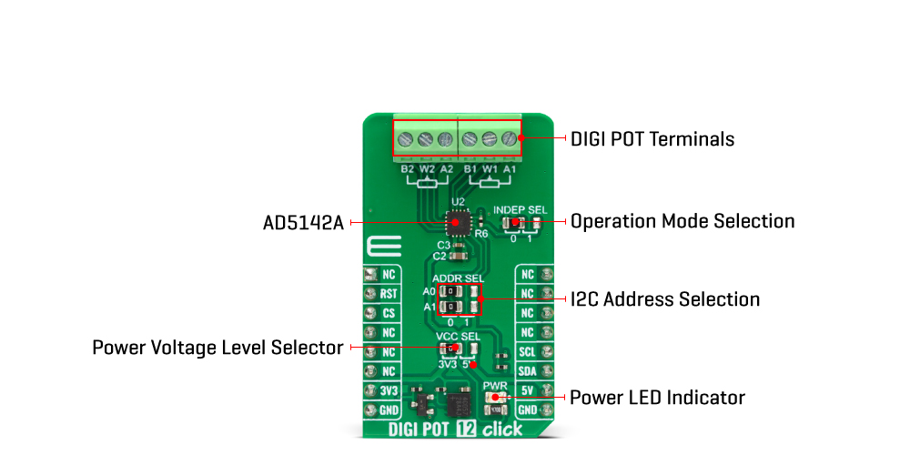
This Click board™ communicates with MCU through a standard 2-Wire I2C interface and operates at Standard (100KHz) and Fast (400KHz) data transfer modes. The I2C address can be selected via the ADDR SEL jumpers with 0 selected by default. There is an RST pin for resetting the digital potentiometers RDAC registers from EEPROM, with active LOW logic. In addition, this Click board™ comes with the INDEP SEL jumper that allows you to choose between the potentiometer and the linear gain setting mode, with the potentiometer mode set by default (0).
The linear gain setting mode of operation can control the potentiometer as two independent rheostats connected at a single point. Once the jumper is set, it can not be disabled by software. In addition, there is a burst mode in which multiple data bytes can be sent to the host MCU. The Shutdown mode places the RDAC in a zero power consumption while the data in EEPROM remains. There is no polarity constraint between the B, W, and A on both terminals, but they can not be higher than the VCC (5V maximum) nor lower than the VSS (0V).
This Click board™ can operate with either 3.3V or 5V logic voltage levels selected via the VCC SEL jumper. This way, both 3.3V and 5V capable MCUs can use the communication lines properly. However, the Click board™ comes equipped with a library containing easy-to-use functions and an example code that can be used, as a reference, for further development.
SPECIFICATIONS
Type Digital potentiometer Applications Can be used for the development of mechanical potentiometer replacements, voltage-to-current conversions, gain and offset adjustment, and many other applications On-board modules AD5142A - digital potentiometer from Analog Devices Key Features Dual-channel, 256-position resolution, 10kΩ nominal resistance, I2C-compatible interface, nonvolatile memory stores wiper settings, 50 years of typical data retention, and more Interface I2C Compatibility mikroBUS Click board size M (42.9 x 25.4 mm) Input Voltage 3.3V or 5V


