


 수량을 선택해주세요.


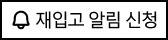
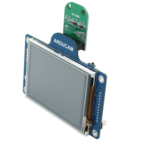
아두캠 디스플레이 쉴드 및 OV2640 카메라
(ArduCAM Display Shield + OV2640 Camera)
개요
- 본 제품은 아두캠 카메라 쉴드와 OV2640 아두캠 카메라가 포함된 제품입니다.
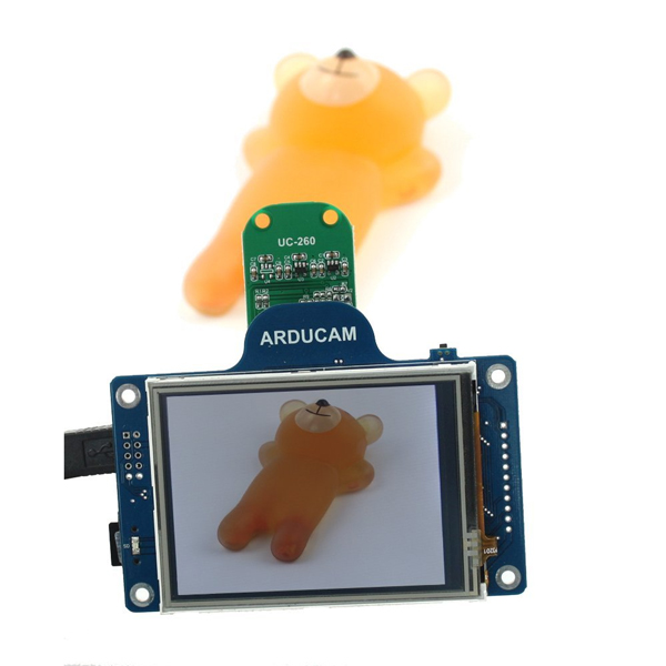
- 아두캠 카메라 쉴드는 아두이노를 위한 범용 카메라 제어 보드로 복잡한 카메라 제어를 쉽게 할 수 있는 인터페이스를 제공합니다.
- 소스코드 라이브러리와 데모코드를 제공하며, 쉴드는 0.3MP - 5MP의 다양한 카메라를 지원합니다.
- 쉴드는 최대 5MP JPEG 이미지를 캡쳐할 수 있습니다.
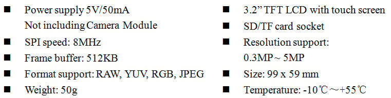
특징
- Support 0.3MP~5MP camera modules, see Table 1
- 3.2 inch TFT LCD with touch screen
- Build in SD/TF card socket
- Support JPEG compression mode, single and multiple shoot mode, one time capture multiple read operation, burst read operation, low power mode and etc.
- Support almost all microcontroller platform,
- Provide open source code library, please visit github.org/arducam
- All ArduCAM’s IO ports are 5V/3.3V tolerant
- Well mated with standard Arduino boards
-
Table 1 Supported Camera Modules
Resolution Sensor Vendor Camera Module Manufacture 0.3MP Omnivision OV7660 / OV7670 / OV7675 /OV7725 ArduCAM 0.3MP Aptina MT9V111 ArduCAM 1.3MP Aptina MT9M112 / MT9M001 ArduCAM 2MP Omnivision OV2640 ArduCAM 2MP Aptina MT9D111 / MT9D112 ArduCAM 3MP Omnivision OV3640 ArduCAM 3MP Aptina MT9T112 ArduCAM 5MP Omnivision OV5640 / OV5642 ArduCAM -
Key Specifications
Pin Out
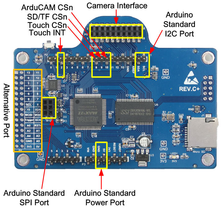
Block Diagram
Figure 3 shows the block diagram of ArduCAM shield which is composed by the camera module, LCD screen and an ArduChip. The camera module is changeable. The ArduChip uses ArduCAM proprietary third generation camera controller technology which handles the complex camera, memory, LCD and user interface hardware timing and provides a user friendly SPI interface.

Functions
Single capture mode is the default capture mode of the camera. After issuing a capture command via SPI port, the ArduCAM will wait for a new frame and buffer the one entire image data to the frame buffer, and then assert the completion flag bit in the register. User only needs to poll the flag bit from the register to check out if the capture is done.
Multiple capture mode is advanced capture mode. By setting the number of frames in the capture register, the ArduCAM will capture consequent frames after issuing capture command. Note that number of frames should be set properly and make sure do not exceed the maximum memory space.
The JPEG compression function is implemented in the image sensor. With proper register settings to the sensor, user can get different resolution with JPEG image stream output. It is recommended to use JPEG output to get higher resolution than RGB mode, due to the limitation of frame buffer.
Normal read operation reads each image data by sending a read command in one SPI read operation cycle. While burst read operation only need to send a read command then read multiple image data in one SPI read operation cycle. It is recommended to use burst read operation to get better throughput performance.
Sometimes user wants to read the same frame of image data multiple times for processing, the rewind read operation is designed for this purpose. By resetting the read pointer to the beginning of the image data, user can read the same image data from the start point again.
Some battery power device need save power when in the idle status, the ArduCAM offers the low power mode to reduce power consumption, by shutdown the sensor and memory circuits.
Image sensor control function is implemented in the image sensor. By setting proper set of register settings, user can control the exposure, white balance, brightness, contrast, color saturation and etc.


문서
연관제품
- 연관제품 1


