


 수량을 선택해주세요.


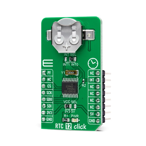
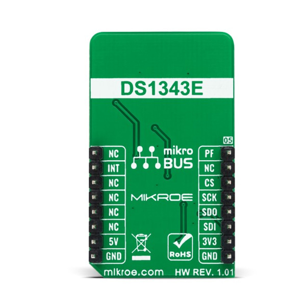
DS1343 RTC 모듈
(RTC 12 CLICK)
개요
- 본 제품은 DS1343 RTC 모듈입니다.
- SPI로 설정이 가능한 RTC DS1343 칩을 기반으로 디자인된 제품입니다.
- 3.3V/5V 시스템과 사용이 가능합니다.
특징
-
Type RTC Applications Can be used for portable applications, industrial and health-related time metering applications, and others requiring an accurate RTC for their operation. On-board modules DS1343 - low-current RTC that consumes an extremely low timekeeping current permitting longer life from a backup supply source from Maxim Integrated Key Features Low power consumption, low timekeeping current of 250nA, RTC counts seconds, minutes, hours, days, dates, months, and years with year compensation valid through 2099, power-fail and switch circuitry, 96B battery-backed NV RAM, and more. Interface SPI Compatibility mikroBUS Click board size M (42.9 x 25.4 mm) Input Voltage 3.3V or 5V RTC 12 Click as its foundation uses the DS1343, a low-current RTC that consumes an extremely low timekeeping current permitting longer life from a backup supply source from Maxim Integrated. The devices provide a full binary-coded decimal clock calendar accessed by a simple serial interface. The clock/calendar provides seconds, minutes, hours, day, date, month, and year information. The month's end date is automatically adjusted for months with fewer than 31 days, including corrections for leap year through 2099. The clock operates in either a 24-hour or 12-hour format with an AM/PM indicator.
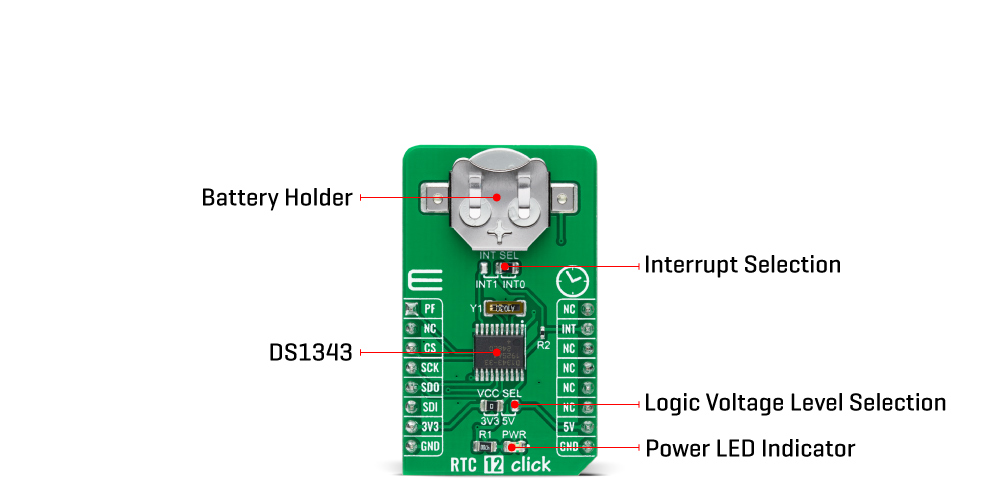
As performed on this Click board™, the most common configuration is a battery-backed up RTC, which maintains time and may hold data in 96 bytes of NV RAM provided for data storage. In addition to the DS1343, the RTC 12 Click is equipped with a button cell battery holder compatible with the 3000TR battery holder, suitable for 12mm Coin Cell batteries. Furthermore, it also has a built-in temperature-compensated power-sense circuit that detects power failures and automatically switches to the backup supply, thus allowing for uninterrupted operation.
The DS1343 communicates with MCU using the standard SPI serial interface that supports modes 1 and 3 with a maximum frequency of 4 MHz. It also provides two programmable time-of-day alarms. Each alarm can generate an interrupt on a programmable combination of seconds, minutes, hours, and days, available on the INT pin of the mikroBUS™ socket. The interrupt selection can be made by positioning the SMD jumper labeled INT SEL to an appropriate position. Both interrupt outputs operate when the device is powered by mikroBUS™ power rails or backup supply voltage.
In addition to the features mentioned above, the user can use another additional indicator routed to the AN pin of the mikroBUS™ socket labeled as PF to indicate a loss of a primary power supply, VCC from mikroBUS™ power rails.
This Click board™ can operate with both 3.3V and 5V logic voltage levels selected via the VCC SEL jumper. This way, it is allowed for both 3.3V and 5V capable MCUs to use the SPI communication lines properly. In addition, however, the Click board™ comes equipped with a library containing easy-to-use functions and an example code that can be used, as a reference, for further development.


