


 수량을 선택해주세요.


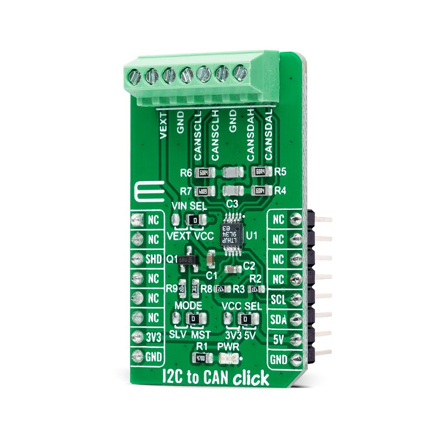
I2C - CAN 트랜시버 모듈 -LT3960
(I2C TO CAN CLICK)
개요
- 본 제품은 I2C - CAN 트랜시버 모듈 -LT3960입니다.
- 싱글 마스터 I2C 버스를 CAN버스로 확장가능하게 하여 주는 제품으로 LT3960 칩을 탑재하고 있습니다.
- 최대 400kbps의 I2C 통신이 가능합니다.
- 3.3V/5V 시스템과 사용이 가능합니다.
특징
-
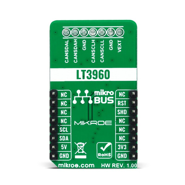
Type CAN Applications Can be used for industrial and automotive networking, remote sensor applications, and more. On-board modules LT3960 - I2C to CAN-Physical transceiver used to send and receive I2C data up to 400kbps using the CAN-Physical layer for differential signaling over twisted pair connections from Analog Devices Key Features High speed I2C to CAN-physical transceiver, up to 400kbps I2C communications, up to 60V power supply, low current Shutdown mode, and more. Interface I2C Compatibility mikroBUS Click board size M (42.9 x 25.4 mm) Input Voltage 3.3V or 5V,External I2C to CAN Click as its foundation uses the LT3960, I2C to CAN-Physical transceiver used to send and receive I2C data up to 400kbps using the CAN-Physical layer for differential signaling over twisted pair connections from Analog Devices. Using two integrated CAN transceivers, the LT3960 creates a differential proxy for each single-ended I2C clock and data signal capable of crossing harsh or noisy environments across two twisted pairs. Each transceiver consists of a transmitter and receiver, capable of quickly converting I2C dominant signal into a differential dominant signal and vice versa. Also, it extends functionality in environments with high common-mode voltages due to electrical noise or local ground potential differences.
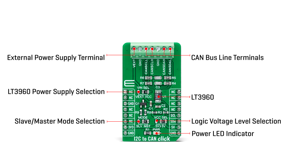
I2C to CAN Click communicates with MCU using the standard I2C 2-Wire interface to read data and configure settings, supporting Fast Mode operation with a clock frequency up to 400kHz. The LT3960 provides a mode selection feature selectable via jumper labeled as MODE, where the user can choose between Master or Slave mode of operation. The SHD pin routed to the CS pin of the mikroBUS™ socket is used to put the LT3960 in a low-power Shutdown mode, disabling both the LDO and transceivers and allows selection between Master and Slave modes when enabled.
The selection between Master and Slave mode is performed by positioning the SMD jumper labeled as MODE to an appropriate position marked as SLV and MST. When a jumper is on the MST position, Master mode is selected, and the EN/MODE pin of the LT3960 is tied to a high logic state, while floating this pin, more precisely positioning the SMD jumper to an SLV position, allows the user to select Slave mode of operation.
This Click board™ can operate with both 3.3V and 5V logic voltage levels selected via the VCC SEL jumper. It allows for both 3.3V and 5V capable MCUs to use the I2C communication lines properly. Additionally, there is a possibility for the LT3960 power supply selection via jumper labeled as VIN SEL to supply the LT3960 from an external power supply terminal in the range from 4 to 60V or with VCC voltage levels from mikroBUS™ power rails. However, the Click board™ comes equipped with a library containing easy-to-use functions and an example code that can be used, as a reference, for further development


