


 수량을 선택해주세요.


I2C 멀티플렉서 모듈 -LTC4306
(I2C MUX 5 CLICK)
개요
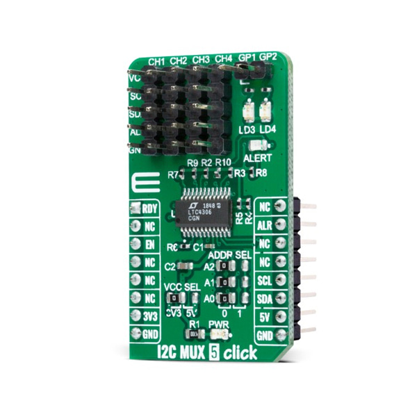
- 본 제품은 I2C 멀티플렉서 모듈 -LTC4306 입니다.
- LTC4306 칩을 기반으로 디자인된 4채널 2선 버스 I2C 멀티플렉서로 버스 버퍼를 제공하여 업다운 스트림에 대해 정전식 절연을 제공합니다.
-
특징
-
Type I2C Applications Can be used for a wide range of applications from industrial to medical, communications, and automotive systems. On-board modules I2C MUX 5 Click is based on the LTC4306, a 4-channel, 2-wire bus multiplexer with bus buffers to provide capacitive isolation between the upstream and downstream buses from Analog Devices. Key Features Multiplexer with capacitance buffering, programmable disconnect from stuck bus, compatible with I2C and SMBus standards, several fault reporting pins, and more. Interface I2C Compatibility mikroBUS Click board size M (42.9 x 25.4 mm) Input Voltage 3.3V or 5V -
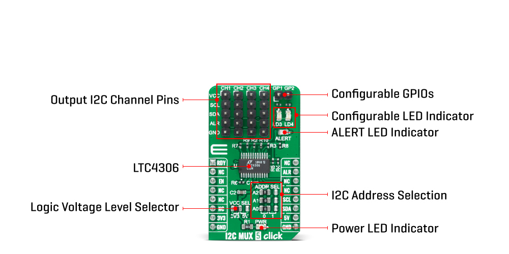
I2C MUX 5 Click communicates with MCU using the standard I2C 2-Wire interface with a frequency up to 400kHz. It also has three address pins (A0, A1, and A2 that provides 27 specific addresses) programmed by the user to determine the value of the last three LSBs of the slave address selected by onboard SMD jumpers labeled as ADDR SEL, allowing selection of the slave address LSBs.
In addition to I2C communication, this Click board™ has several additional features such as Interface Enable, Fault Alert, and Connection Ready function. The Fault Alert pin, labeled as ALR and routed on the INT pin of the mikroBUS™ socket, is pulled low when a fault occurs to alert the MCU. This pin is pulled to low logic level when any of the four alert input pins are low or when the 2-wire bus is stuck low and visually displays its function with a red LED marked as ALERT.
The Enable pin, labeled as EN and routed on the CS pin of the mikroBUS™ socket, is used to enable or disable I2C communication to the LTC4306, and the Ready pin labeled as RDY, routed on the AN pin of the mikroBUS™ socket, is used as connection ready output. This pin is pulled down when none of the downstream channels is connected to the upstream bus and turns off when one or more downstream channels are connected to the upstream bus.
The LTC4306 optionally provides two general-purpose input/output pins (GPIOs) that can be configured as logic inputs, open-drain outputs, or push-pull outputs. These pins are also connected to the two green LEDs, LD3 and LD2, which light up when GP1 and GP2 pins, respectively, are low.
This Click board™ is designed to operate with both 3.3V and 5V logic voltage levels selected via the VCC SEL jumper. It allows for both 3.3V and 5V capable MCUs to use the I2C communication lines properly. However, the Click board™ comes equipped with a library that contains functions and an example code that can be used, as a reference, for further development.


