


 수량을 선택해주세요.


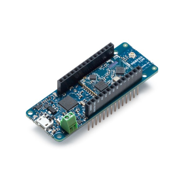
아두이노 MKR FOX 1200 보드 -SigFox ATA8520
(ARDUINO MKR FOX 1200 W/O ANTENNA)
개요
특징
-
Microcontroller SAMD21 Cortex-M0+ 32bit low power ARM MCU Board Power Supply (USB/VIN) 5V Supported Batteries(*) 2x AA or AAA Circuit Operating Voltage 3.3V Digital I/O Pins 8 PWM Pins 12 (0, 1, 2, 3, 4, 5, 6, 7, 8, 10, A3 - or 18 -, A4 -or 19) UART 1 SPI 1 I2C 1 Analog Input Pins 7 (ADC 8/10/12 bit) Analog Output Pins 1 (DAC 10 bit) External Interrupts 8 (0, 1, 4, 5, 6, 7, 8, A1 -or 16-, A2 - or 17) DC Current per I/O Pin 7 mA Flash Memory 256 KB SRAM 32 KB EEPROM no Clock Speed 32.768 kHz (RTC), 48 MHz LED_BUILTIN 6 Full-Speed USB Device and embedded Host LED_BUILTIN 6 Antenna power 2dB Carrier frequency 868 MHz Working region EU Lenght 67.64 mm Width 25 mm Weight 32 gr.
문서
-
OSH: Schematics
The MKR FOX 1200 is open-source hardware! You can build your own board using the following files:
EAGLE FILES IN .ZIPSCHEMATICS IN .PDFFRITZING IN .FZPZ
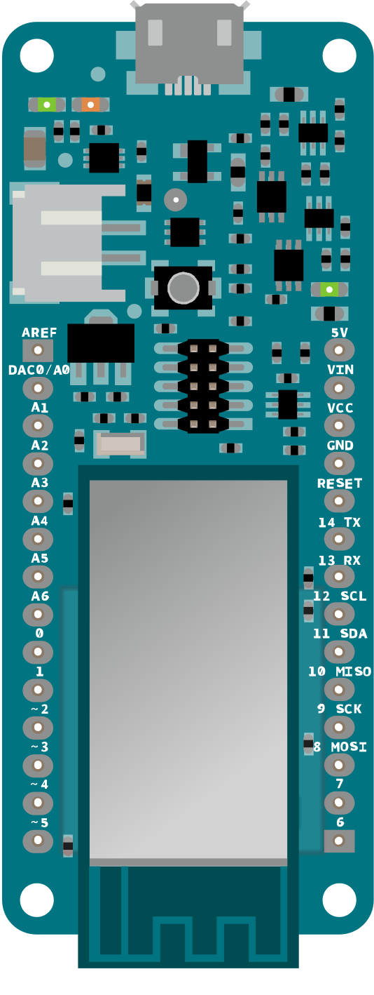
Pinout
Download the pinout in PNG format
Coverage
Check your area coverage on the SigFox website
Data planningThe MKRFOX1200 price includes a subscription to the SigFox network for one year. The plan will be automatically activated after the fourth message has been sent. You can send up to 140 messages per day.
Antenna
The MKR FOX 1200 requires a GSM antenna that can be attached to the board with the micro UFL connector; please check that it can accept frequencies in the SigFox's range (868 Mhz).
Please note: for best result, do not attach the antenna to a metallic surface like car chassis, etc.
Batteries, Pins and board LEDs
Battery capacity: The connected batteries must have a nominal voltage of 1.5V
Battery connector: If you want to connect a battery pack (2x AA or AAA) to your MKR FOX 1200 use the screw terminal block.
Polarity : as reported on the silk in the bottom of the board, positive pin is the closest to the USB connector
Vin: This pin can be used to power the board with a regulated 5V source. If the power is fed through this pin, the USB power source is disconnected. This is the only way you can supply 5v (range is 5V to maximum 6V) to the board not using USB. This pin is an INPUT.
5V: This pin outputs 5V from the the board when powered from the USB connector or from the VIN pin of the board. It is unregulated and the voltage is taken directly from the inputs.
VCC: This pin outputs 3.3V through the on-board voltage regulator. This voltage is 3.3V if USB or VIN is used and equal to the series of the two batteries when they are used
LED ON: This LED is connected to the 5V input from either USB or VIN. It is not connected to the battery power. This means that it lits up when power is from USB or VIN, but stays off when the board is running on battery power. This maximizes the usage of the energy stored in the battery. It is therefore normal to have the board properly running on battery power without the LED ON being lit.
On board LED: On MKRFOX1200 the onboard LED is connected to D6 and not D13 as on the other boards. Blink example or other sketcthes that uses pin 13 for on board LED may need to be changed to work properly.


