수량을 선택해주세요.


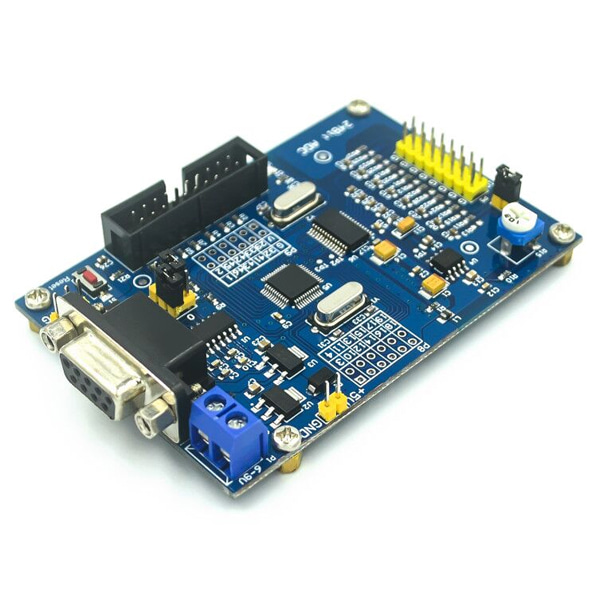
ADS1256 24비트 ADC 보드 -STM32F103
(ADS1256 24-bit ADC STM32F103 Board)
개요
- 본 제품은 ADS1256 24비트 ADC 보드 -STM32F103입니다.
- ADS1256 24비트 ADC 칩과 STM32F103 MCU를 탑재하고 있는 제품입니다.
- 8개 채널에 대해 ADC 입력을 받을 수 있는 제품입니다.
특징
-
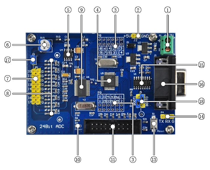
1. Power input terminal, input voltage range 5.5V - 12V (5V power supply, please connect directly to 2);2. 5V power supply input terminal (1.2 two power supplies, only one can be connected);3. STM32F103C8T6 leads GPIO, which is convenient for secondary development. The silk screen directly corresponds to the pin number of the chip;4. Brand new original master MCU: STM32F103C8T6;5. 2.5V benchmark, ultra-high precision, low temperature drift;6. Adjustable potentiometer, the output adjustable voltage is linked to AIN0/ I0;7. Collect 8 channels of input, I0-I7 is connected to the positive terminal of the acquisition voltage, G is the analog ground, and the negative terminal of the acquisition voltage is connected;8. Input filter and attenuation resistor, default is not attenuated, leaving the position of solder attenuation resistor, 0603 package;9. ADS1256IDB acquisition chip, new original imported;10. Power indicator LED;11. JTAG interface, designed according to JLINK-V8 or V9 definition;12. Not marked;13. STM32F103C8T6 reset button;14. USB to TTL wiring, corresponding to the MCU's TX, RX, GND, can communicate directly with the computer;15. Original imported 3232 serial communication chip;16. Serial port header, female head;17. Adjustable potentiometer output voltage to I0 / AIN0 on/off control: Disconnect IO floating, connect I0 to measure adjustable potentiometer output voltage terminal;18. STM32 BOOT0 and BOOT1 select control jump caps;
문서
- document link https://pan.baidu.com/s/1dJYf-pL_mb_0rlTlbUPqWA password: 1234
-
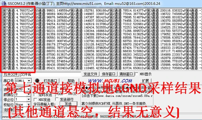
The measured results of the ground show: the unit of attention is uV
As shown in the figure below: the capture card is powered on. Di seven uses channel I7 and analog ground AGND (G) to short the jump cap, measure the analog ground. The size of the measurement result directly reflects the layout and layout of the board, and the filtering is good or bad. The smaller the sampling result, the better the fluctuation. The smaller the better, the better. For many sample tests, the sampling voltage is in a few uV. Many other boards have a sampling voltage of several hundred uV, and this sampling voltage will be directly coupled to the back. Sampling results, resulting in loss of precision
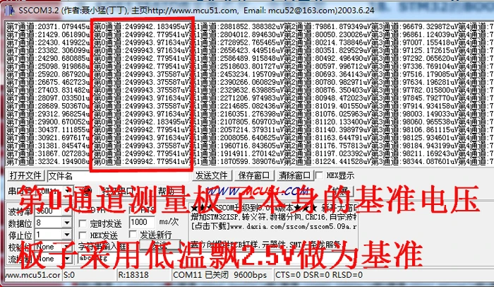
The measured results of the reference voltage are displayed: the unit of attention is uV
As shown in the figure below: The reference power supply of the acquisition card adopts low temperature drift. Ultra-high precision 2.5V is used as the reference source. Since the reference source is a very stable signal, directly collecting a stable signal can also reflect the accuracy of a capture card. And stability, Di0 channel connected to the reference power supply 2.5V, the sampled results are shown in the figure below, consistent with the test results of the six and a half.
 Basic parameters of 8-channel (24bit) A/DC converter board:Size: 82.8mm X 53.4mmPlate thickness: 1.6mmChip model: STM32F103C8T6 (single chip), ADS1256 (24-bit precision AD conversion chip)Power supply voltage: on-board 5V and 3.3V regulator components, 9V external DC power supply can be used, and the power supply has anti-reverse functionCrystal frequency: 8MHZ, 9 times internal frequency of the chip, working frequency 72MHZ.8-channel (24bit) A/DC converter board Hardware teity:The AD chip has a reference voltage of 2.5V and is generated by a precision voltage regulator.A potentiometer is set on the board to test the AD input. The voltage generated by the voltage divider of the potentiometer is connected to AN0 through the S3 jumper. It is suitable for debugging the board without the sensor. If this test is not used, the S3 jumper can be taken. Off, input the test voltage directly from AN0--AN7. (The voltage input to the AD input cannot be higher than 5V)
The following describes the specific functions of the three modes one by one://模式1:Continuously acquire single-channel AN0 analog voltage for ADC conversion, and calculate the converted data as voltage value, send data out through serial port in ASCII code form. In this mode, serial port assistant software can directly read voltage, suitable for software development. Engineers use it because they don't need to know any principles of microcontroller hardware.The collected data shows the following example. This acquisition is the result of connecting the voltage to the Di0 channel (AN0). The measurement accuracy is very stable in the range of 0.0001V (ie 0.1mV). The remaining channels are vacant.Since the transmission is ASCII code, the serial port software of the host computer should select "character (ASCII) display", do not select hexadecimal display, otherwise it will display garbled characters.//模式2:Continuously collect 8 channels of analog voltage for 24-bit ADC conversion, and calculate the converted data as voltage value, send the data through the serial port in ASCII code form. In this mode, the serial port assistant software can also directly read the voltage, suitable for Software development engineers use it because there is no need to understand any principles of microcontroller hardware.The collected data shows the following example://模式3:
Fully differential input mode, measuring voltage range is -5V~+5V. A total of 4 sets of differential inputs. Suitable for sensors connected to electronic scales.
The corresponding input pins are:AN0-------Channel 0 (V0) + InputAN1-------Channel 0 (V0) - InputAN2-------Channel 1 (V1) + InputAN3-------Channel 1 (V1) - InputAN4-------Channel 2 (V2) + InputAN5-------Channel 2 (V2) - InputAN6-------Channel 3 (V3) + InputAN7-------Channel 3 (V3) - Input


 "19세 미만의 미성년자"는 출입을 금합니다!